Category Archives: Model Making Process

3D Printer in the Model Shop

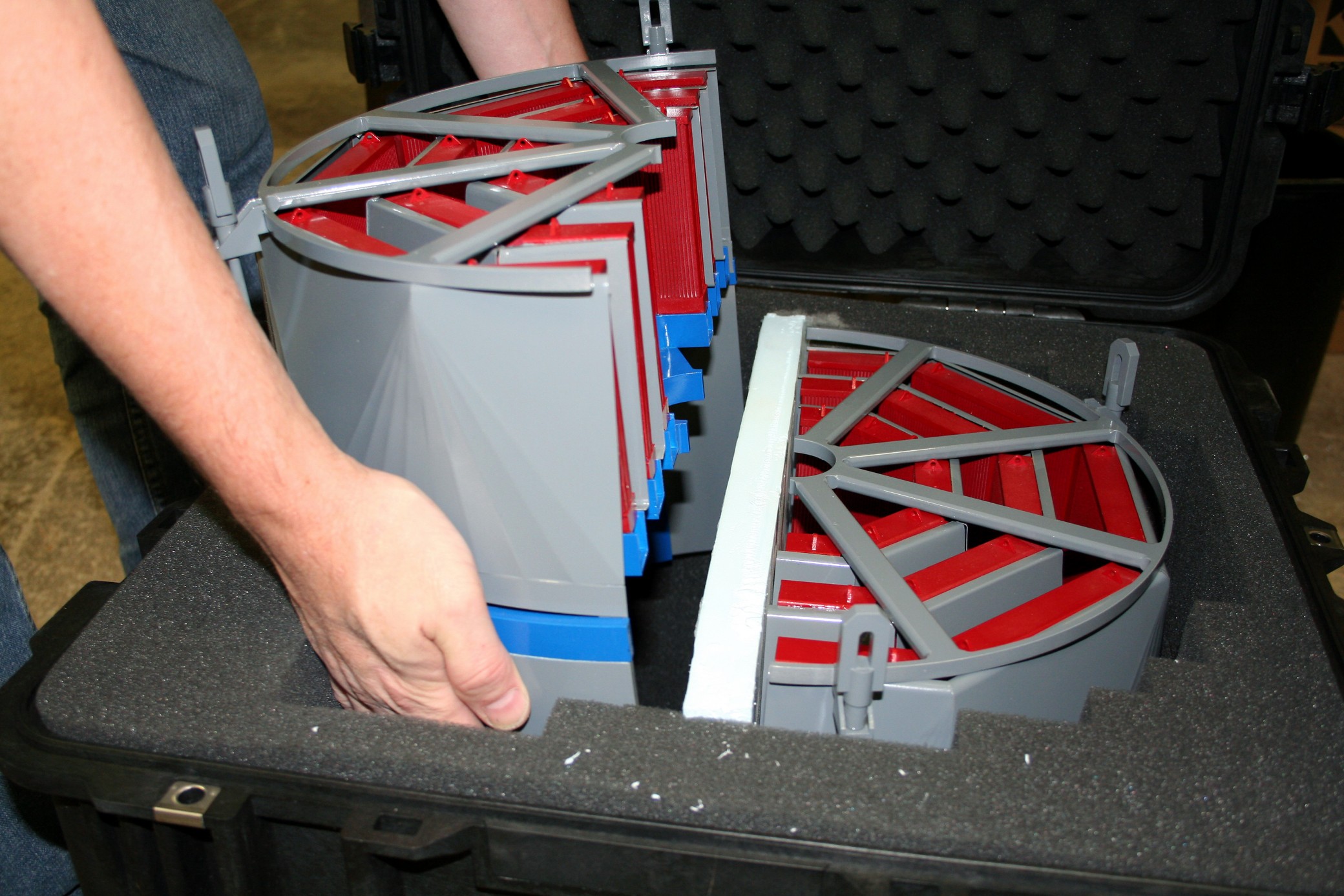
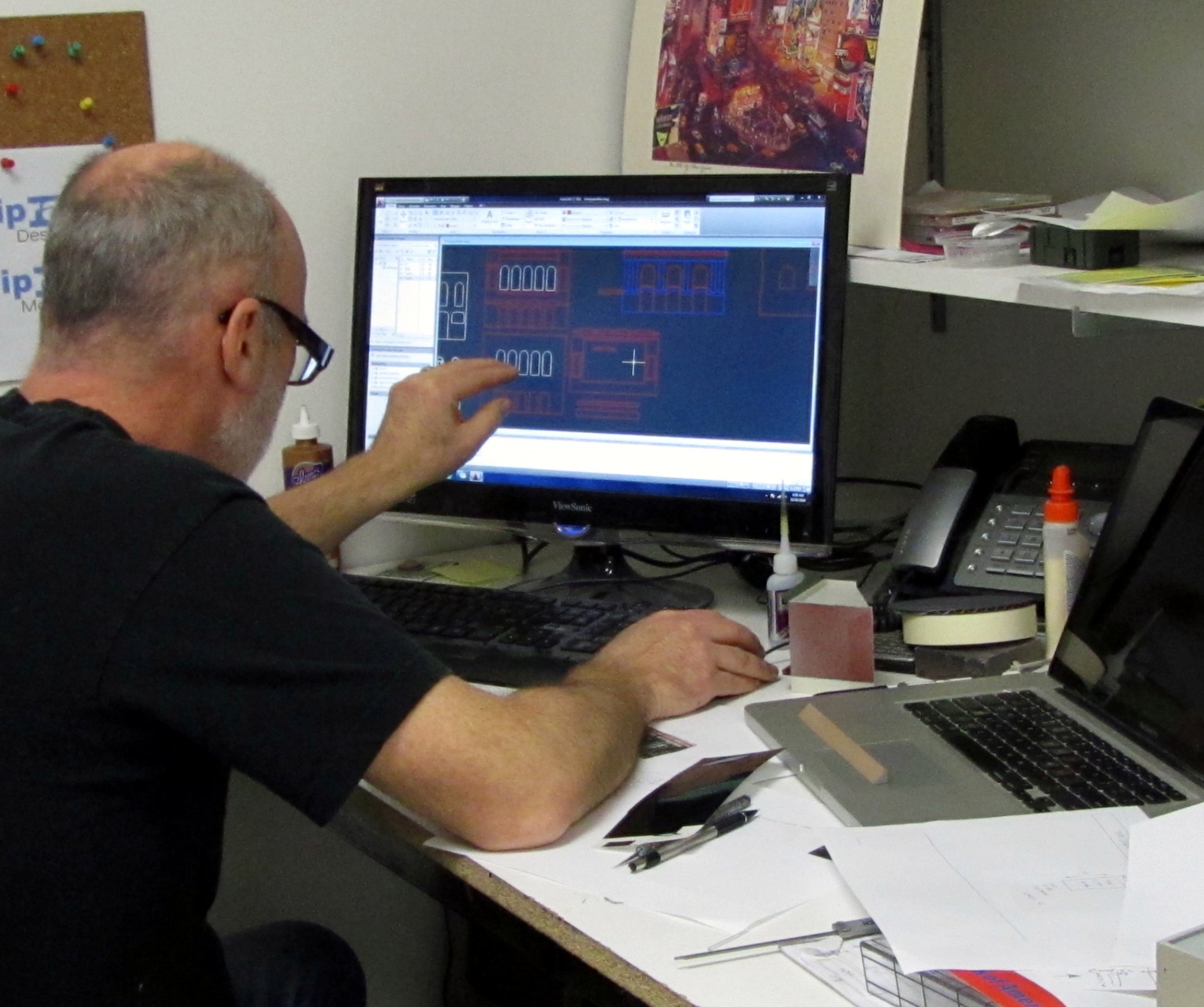
We’re getting ready at the model shop for a new 3D printer. This machine will introduce additive processes for model making designed to increase flexibility and productivity.

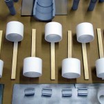
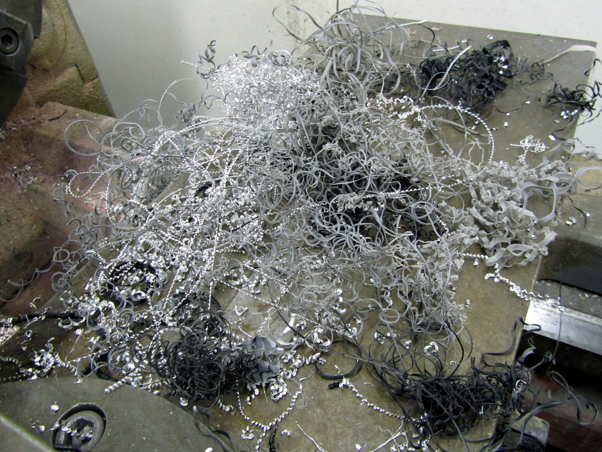
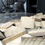
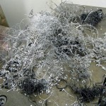
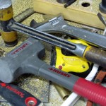
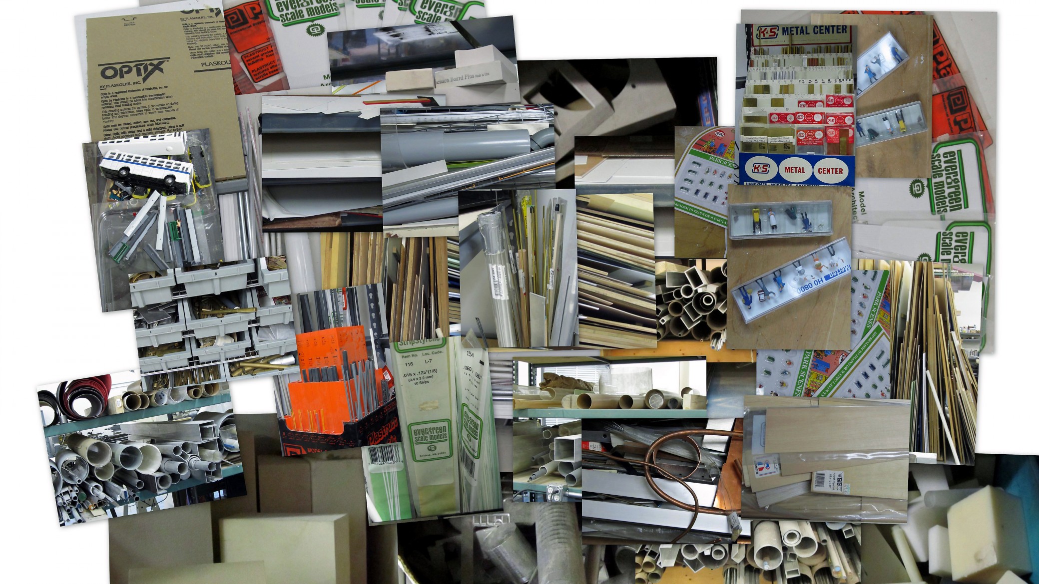
Model making has traditionally been associated with a subtractive method of fabrication. Meaning, model parts are formed by taking something away from a material through carving, sculpting, cutting, sanding or  chopping.  These extracted parts are then glued together to form the whole model.

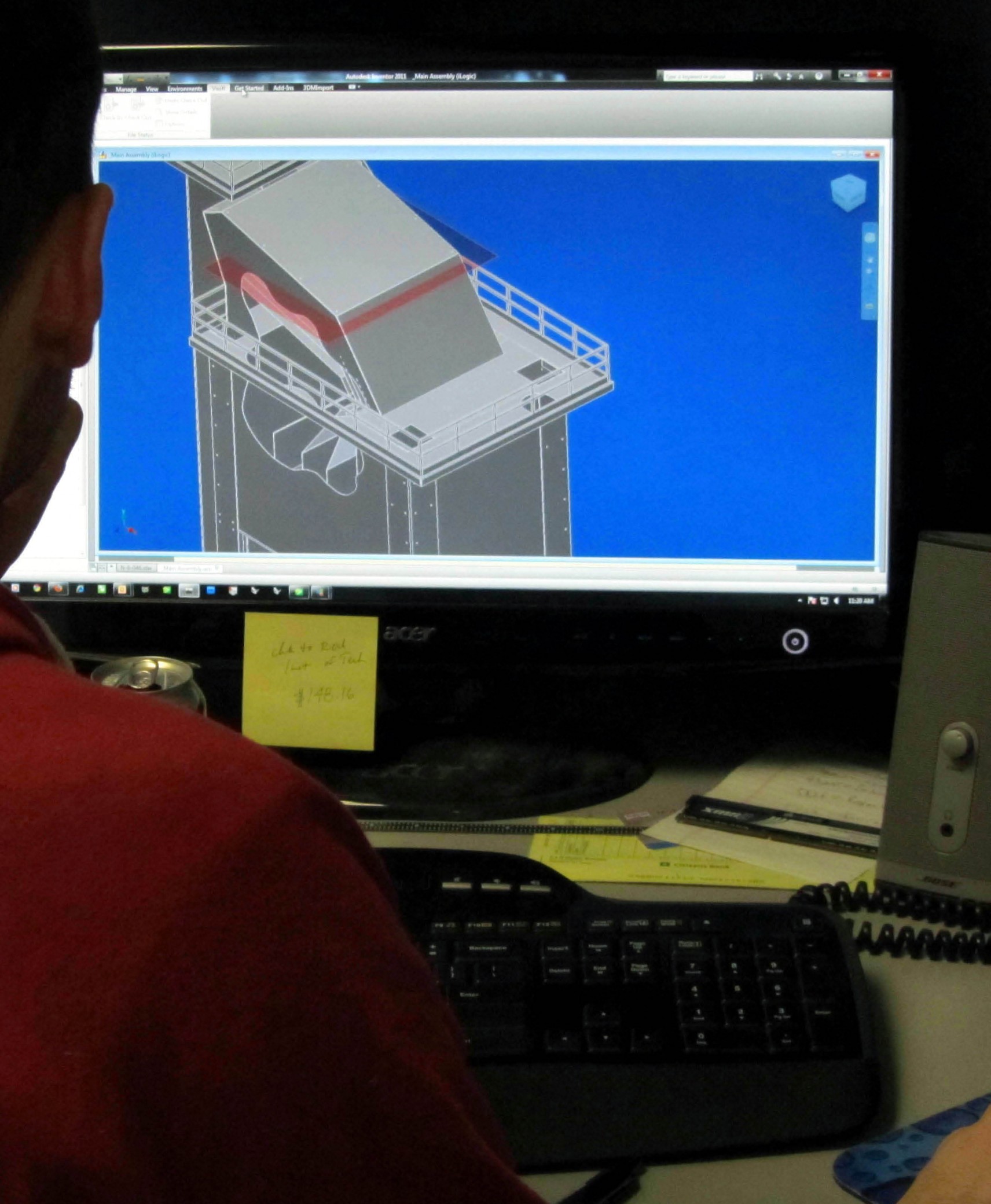
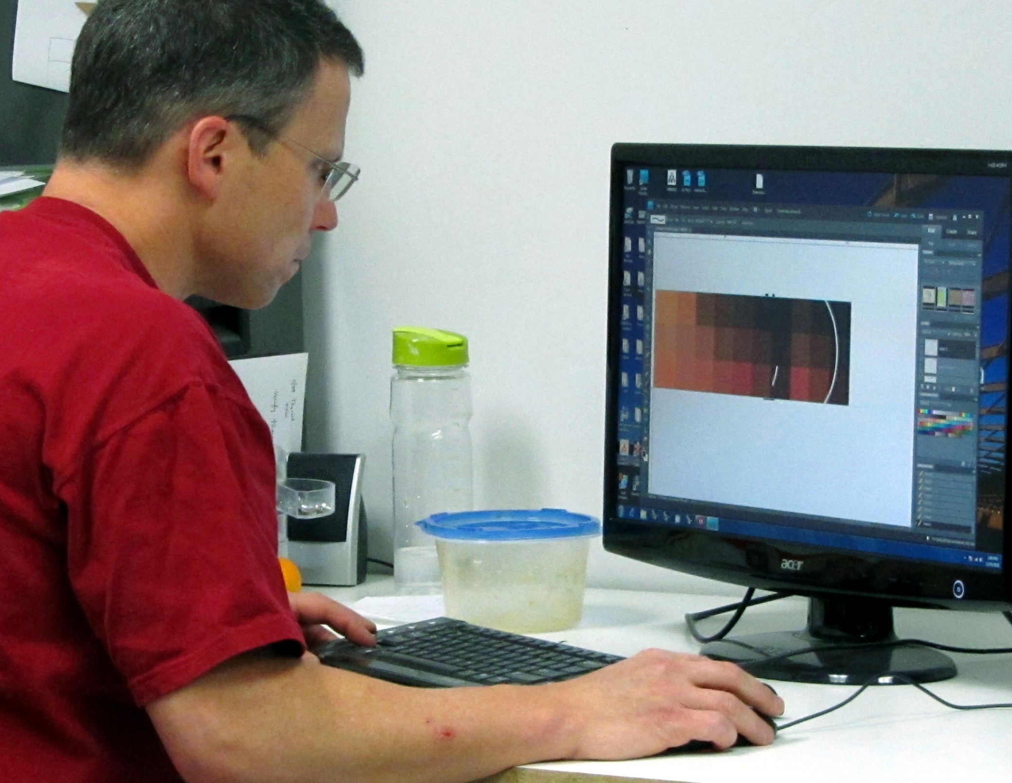
Additive methods of model fabrication do the opposite. Instead of sculpting a model out of material by taking away, an object is built up layer by layer. This additive process creates a 3D object from seemingly nothing.  A computer image of the desired part is programmed into the 3D printer.  The machine then creates a solid object by adding successive layers of material in the desired shape and form.

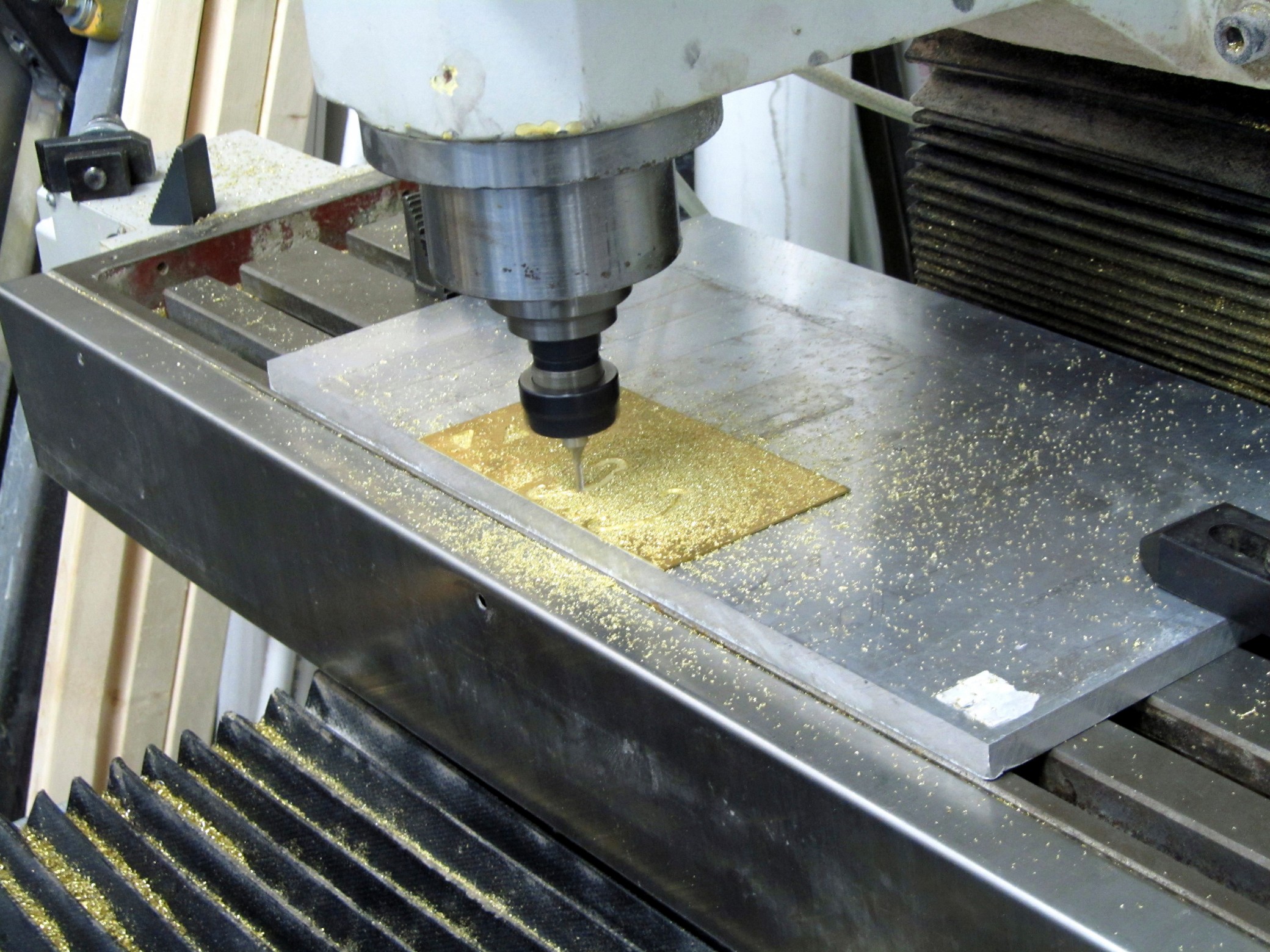
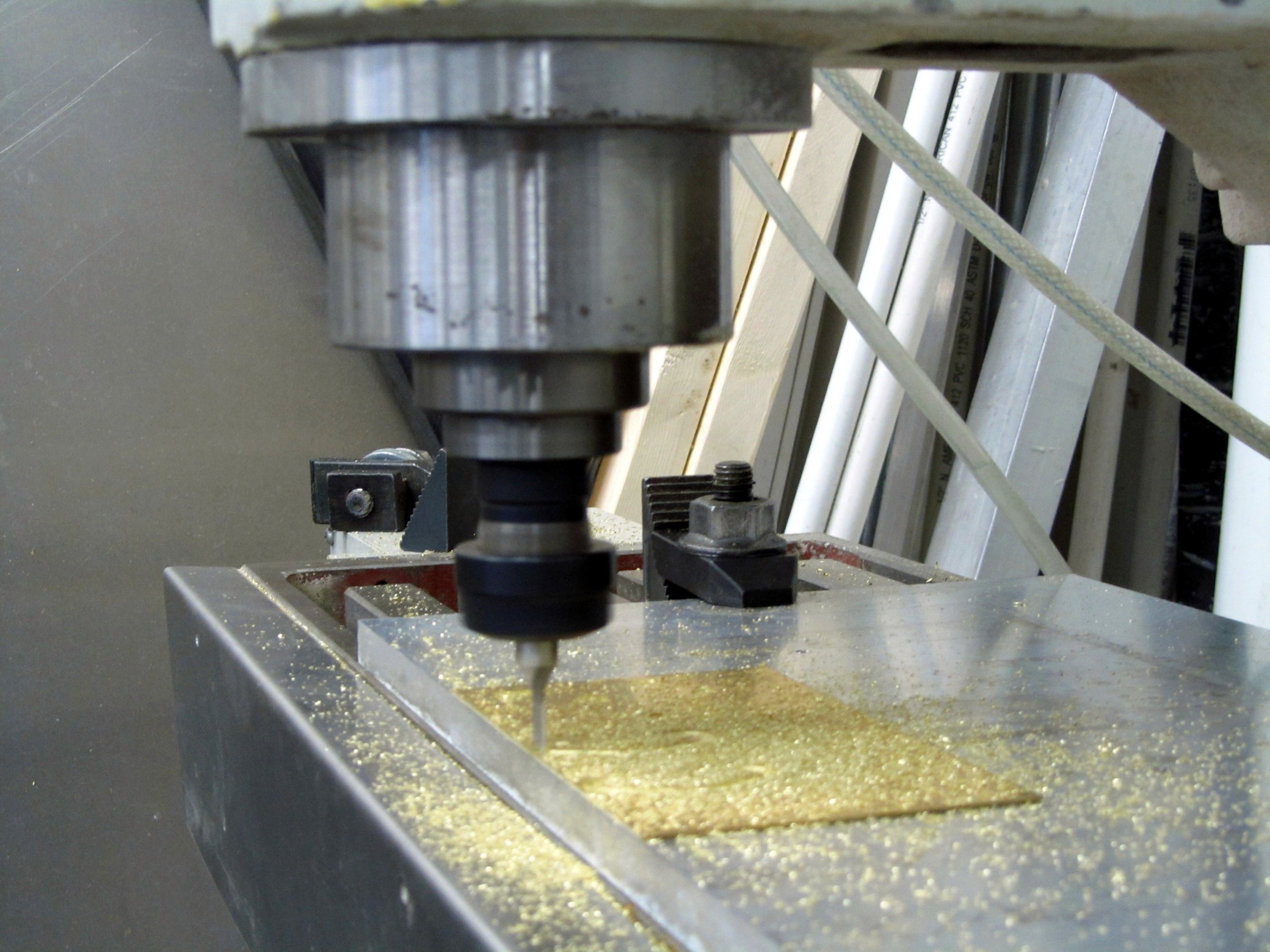
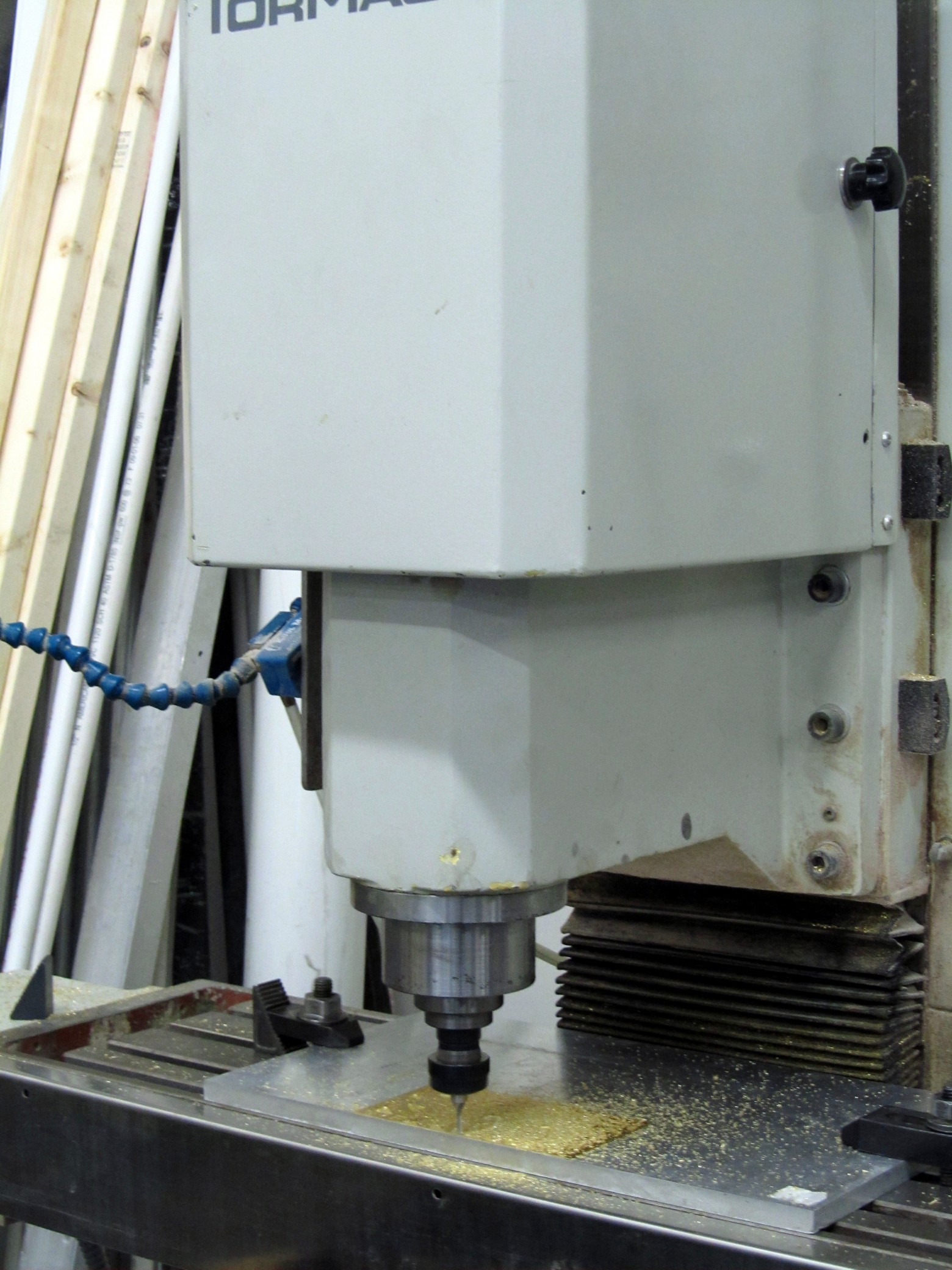
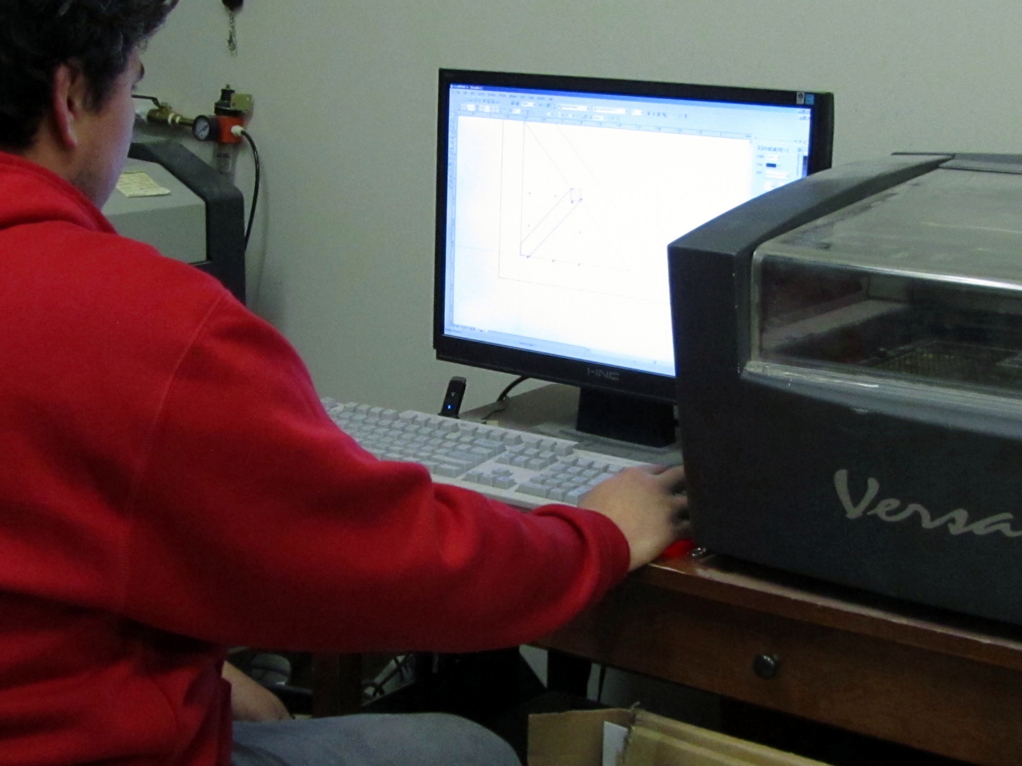
The additive method is fast and efficient, vastly reducing the amount of hand’s on work needed to create a model part. The subtractive method can be sped up as well with the addition of computer numerically controlled (CNC) machines, making rote shaping and carving tasks more autonomous.

These technological advancements  are welcome additions to the model making shop. They cannot replace craftsmanship, experience and artistry. They’re meant to enhance the fabrication process, freeing up our model makers to put their energy and talents toward more essential and complex tasks.

Production Processes for Multiple Scale Models

Custom scale models are often one time only builds. Model makers are given an object, picture or design, they draw up the parts in 3D and set about constructing the item. Whether the finished product ends up in a museum, sales office, board room or trade show booth, it is often a one-of-a-kind model that won’t be repeated.

Occasionally, though, a model shop is given as assignment to make multiple scale models of the same design. Sometimes these are requested all at once, and other times a model shop will repeat models on an as-needed basis.

It is these types of projects that turn the model shop into a temporary production facility of sorts. A systematic approach is developed to create multiple parts in an efficient, orderly fashion. Using fabrication techniques such as casting, CNC milling, 3D printing and lasering, multiples of the same part are created.

When it comes time to assemble parts for duplicate models, jigs are designed. A jig is a tool used to control the location or motion of another tool. The jig’s primary purpose is to provide repeatability, consistency and efficiency.

Creating multiple scale models of the same object requires certain upfront approaches that would be unnecessary for a one-time build. Duplicate models are still custom-built, but fabrication techniques and production processes are controlled and streamlined in order to create a consistent product, over and over, in a reasonable time-frame.

Can a Model Maker use Mass-Produced Parts?

Professional model makers are in the business of building (and sometimes designing) one-of-a-kind creations. Very occasionally, though, a model maker decides that fabricating a particular part from scratch is not in the best interest of the project. In these instances, an existing product might be bought and deconstructed to extract a commodity out (sometimes referred to as “kit bashing”).


These plastic wheels have been removed and reassembled from off-the-shelf toy trucks. They will be added to built-from-scratch trucks. The trucks themselves are not the main focus of the finished model. Ultimately this project will be a training model for a shipping company that would like to have table top practice at the real life task of loading and unloading pallets.

It’s uncommon to find preexisting parts, particularly in the right scale, for a custom model project. Internet searching has made it a bit easier to find a usable commodity. Sometimes it’s a smart choice for a project, and ultimately for the client’s budget, to include ready-made pieces in the construction.

Welding as a Model Making Tool

model maker weldingOne fabrication technique that is not often associated with model making is welding. While styrene plastic and glue are staples of some model designs, many more are made out of metal for stability, longevity and appearance. One way to fasten metal model parts to each other is by welding, or a similar technique: soldering. While not every model maker is skilled in this trade, it’s helpful to have the training and equipment on hand in a professional model shop.

Welding is the process of bonding parts together by applying heat to two pieces of metal and melting them together along with a filler material to form a strong joint when cooled. Soldering is similar but does not actually melt the work pieces themselves, only the filler material between them which has a lower melting point, thus requiring less heat application.

Types of models that may need welding or soldering application vary. If a model needs to hold up to heavy handling by the client it might be considered a good candidate for brass, sheet metal or stainless steel. A more delicate material would not hold up to rigorous use.  As with most models, the purpose or intended use informs the materials and fabrication techniques involved.

Currently KiwiMill has two models in the shop that required welding. One is a large-scale model of an asphalt plant and the other is a model of an expandable shipping container. One of our model makers has apprenticed with another in-house master welder to complete these projects.

model maker welding

Making a Model With Working Parts

scale model working parts

working parts scale model

In the shop right now is a 7 ft asphalt plant model with working parts. Anything that moves in a real asphalt plant will be replicated on the model as well. It won’t actually function as in turning tar & stones into asphalt, but it will be nearly capable of doing so in miniature.

The client wants to demonstrate how the machine operates or how it is controlled. Doors and chutes that are moved primarily by hydraulic cylinders in a real asphalt plant will be demonstrated with 12 volt electric linear actuators on the model. Those parts in a real asphalt plant that move with gear motors – like augers and buckets – will have miniature gear motors on the model.

Our model makers create drawings in AutoCAD of the doors and chutes, in an open position and closed. That way the “throw” can be calculated, which is the amount of swing needed to open them fully. Then it needs to be determined what length actuators will best represent that throw. The working parts on the model need to be built and the actuators installed on them and tested for accuracy. An important factor to consider is whether or not the actuators can show on the finished model design, or need to be imbedded or disguised. In this particular industrial model, the actuators will be part of the visual presentation.

The gear motors are chosen for the model based on the scale speed necessary to make the parts turn. How much torque is needed? – what sort of load does the gear have to move? This will determine how powerful the motor needs to be. Generally if the part needs to move fast, less torque is required and if the part turns slower, more torque is called for. This particular model has a 218:1 gear ratio as the miniature motor needs to move quite a bit of mechanics.

Finally you have to tie together the different voltage strengths of the various actuators and gear motors into a controller that sits in the base of the model. This programmable code (located in a circuit board) will be the power source, or “the brain” of the working model parts. It will control when power is needed and where in the model to send it.

Packing a Scale Model with Care

 A little talked about aspect of a model maker’s job is to figure out how to pack and ship a finished scale model. No matter how intricate and difficult a build might be, nothing compares to the challenge of getting a model safely to the client in one piece. Scale models can be delicate works of art (though certainly not all of them are) and white glove handling by a dedicated carrier is not always feasable. Shipping companies like Fed Ex and UPS are reasonably priced but do not generally ensure (or insure) that models will arrive unscathed. It’s up to the model maker to give as much thought to the way a scale model will be packed as he has to its design and construction. A project isn’t complete until you get word that the model has been received undamaged.

Different packing methods are used for different types of scale models. Smaller projects (under 2×3 ft) are usually packed in premade hard shell boxes called Pelican cases. They come with solid foam inserts that are then carved to fit the model snugly inside. Similar to how a camera or cell phone is sometimes packed when you buy it at a retail store.

Some models are not as hardy and will be unable to lay in the foam openings without damage. These projects are often secured at their base to a crate and the rest of the model is encased in a protective shell and wrapped securely with packing tape. Mummified in a way.

packing scale models

Some crates are built in the model shop, particularly for bigger pieces. Wood crates were custom made for these trade show models, secured on shelves with screws. A local courier then transported the crates to the client.

packing scale models

 A scale model might be delivered by the model making company itself, anchored by way of wooden blocks and screws to the bottom of a truck floor. Some common carriers may pick up a model on a skid or pallet, depending on its over all size. Often the shipper is UPS or Fed Ex. With these carriers, there is a chance of the model being dropped, or otherwise roughly handled and occasionally a project will need to be returned for repairs or the model makers will go on site to fix damage in transit. It’s easily one of the most frustrating parts of the job, but skilled model makers know exactly how to repair their work.

Topography Model Time

Today in the shop our model makers are carving foam. That can only mean one thing – besides a mess – a topography model!  A topography model depicts the 3D nature of a particular terrain, accurately recording elevation levels and identifying specific land forms.

A topography site plan is used for this project.

topography model

topography model

The site plan is then transferred to a foam block for carving. While in the past topographic models were layered up, using cork, mat board or foam core, modern techniques use the opposite process. Starting with a foam block, the relief is then carved out of the solid piece with a router. The depth that the router plunges into the foam is determined by the scale being used on the map. Different colored lines on the map represent different elevations.  Once the routing is complete the different steps created in the foam are then sanded down to make a smooth transition in elevation levels.

topography model

The foam will then be painted, roads glued down and the remaining surface flocked.

topography model

topography model

Why Draw a Scale Model on the Computer?

drawing parts for scale model

Our shop has been working on a project that involves extensive use of 3D mechanical drawings. The scale model, an asphalt plant, will be 7 feet tall when completed. The size and structure of the  scale model requires it to support its own weight and traditional model making materials would not be appropriate. Sheet metal will be used instead, and the parts need to be sent out of the shop to be  laser cut and bent.

 Model makers  typically design a project as they build it, problem solving,  adjusting and refining their techniques as they go. As craftspeople, they can transform a rough idea into something both accurate in design and beautiful to behold.  The sheet metal parts are being sent to a laser cutter unfamiliar with the project’s nuances, so more precise, documented dimensions are needed.

Using a program called Autodesk Inventor, our model makers have drawn up the sheet metal parts on the computer to be sent to the laser cutter. Then the parts will be bent next door at Clad Industries. The finished pieces will arrive back to the model shop for assembly and detailing. Check back for pictures of the finished scale model!

CNC Milling in a Model Shop

The CNC mill is churning out pieces for our latestmodel shop  project. Parts were drawn in AutoCAD or Rhino for a model radar, then processed through VisualMILL. The professional model maker needs to play the role of machinist at times and this program translates rough data about a part, telling the mill how to handle the material. Our vertical mill is digitally automated via computer numerical control (CNC) and while it is capable of 3D cutting, this particular project asked for 2D brass and aluminum parts. This hardier material was used to allow for soldering and screwing parts together, making the model durable enough for repeated trade show use.


Model Making Materials

While plastic is the raw medium of choice in model making, KiwiMill uses a wide variety of materials to construct theirscale models. Depending on the needs of the client – portability, durability, cost, time constraints or ability to reproduce in volume, or the specifics of the project itself – how the model maker visualizes the object being constructed.

Materials may include:

  • Styrene
  • Metal
  • MDF
  • Acetate
  • Foam board
  • Acrylic
  • Wood
  • Tooling Board
  • Plaster
  • Silicone
  • Latex
  • Laminate
  • Fabric

Raw materials for model building

KiwiMill Model Makers All Have Computer Work Stations

A professional model maker understands the creative and judicious use of available technology in the workplace. While nothing can substitute for inborn talent, classical training and years of experience, a master model maker uses modern techniques to make the finished product more accurate, detailed or available in a shorter time frame for a client, without sacrificing quality and craftsmanship.

Computers are an essential technological tool for building models. From reading CAD files at the start of a project and researching additional or missing information, to creating drawings and applying CAM software to the creation of parts, computer work stations are kept busy at KiwiMill.

Three major steps involve the latest computer software and online resources:

  1. Model makers receive and read the various types of files that clients use to convey their ideas. An architect may send AutoCad files, an engineer might use Rhino, or an artist could have Adobe Illustrator designs that need deciphering. Knowing what you are looking at in the various programs, including Revit, Inventor or Corel, and figuring out what needs to be built is an early step in a model’s design.
  2. If all you are given is a photograph to work with the internet becomes an invaluable research tool to find additional photo angles, renderings or drawings – as much information as possible about the object being created. Even a common shape might be found in TurboSquid to assist in making a particular part.
  3. Computer software is then used to draw parts. Researched dimensions of an actual object may be used to create a part drawing. Drawings are either used as patterns to be built by hand or sent to the laser engraver or CNC milling machine for cutting, or the 3D printer.

In the end, nothing substitutes for a model maker’s ability to think inventively throughout a project, determining the best approach for each process and applying hands-on expertise at each step. An experienced model maker embraces modern technology, but also knows that high tech solutions are not always the best answer.


Model Maker Shop Safety

Upon entering the shop portion of KiwiMill, I’m struck by the vast amount of large equipment: machine lathe, various table saws, a turret punch, laser cutter, bridgeport mill, CNC mill, band saw and paint booth. How does a model maker keep it all straight? More to the point, how does he stay safe? Add to the large machinery the hand-held tools for welding, sanding, routing, brazing, soldering, drilling, molding, painting and casting, and it seems clear to me that safety must be as inborn a trait in model makers as the ability to think visually in 3D.

Talking with KiwiMill’s production manager, I find that while safety is inherently part of any good model maker, there are a few simple practices and tips that can help keep a shop injury-free:

Know the equipment you are working with:

  • Visually familiarize yourself with the machine, how it operates, the way the blades are spinning.
  • Know what materials can be cut on it.
  • Understand the nuances of the equipment, what its reputation is and what can go wrong.
  • Be aware of where your hands are, and where they’ll end up if the material you are working with breaks, flies off or disintegrates.
  • Predict what direction a piece will go if it comes loose and position your body out of that pathway.
  • Find out what debris (dust, chips) will be coming off the product and use goggles and/or mask as needed for protection.
  • Read up on the Material Data Safety Sheet of a particular substance to understand its particular properties.

A confident, proactive attitude works best:

  • Always ask someone if you don’t know how to operate a piece of equipment.
  • Stay focused on the task you are performing.
  • Have a healthy respect for the machine but don’t approach it with fear.
  • Don’t rush through a movement.
  • Take breaks from repetitive or frustrating activity.
  • Watch out for each other while operating equipment. Notice if something looks or sounds strange and don’t hesitate to point it out.

Keep a well-maintained and well-stocked shop:

  • Have plenty of fire extinguishers throughout the shop.
  • Provide goggles, safety glasses, headphones and masks.
  • Clean up spills immediately.
  • Contain oily rags, and towels in a special bin to avoid spontaneous combustion.
  • Keep machines and tools well maintained and blades sharpened regularly.
  • Don’t allow loose clothing or any dangling objects near a rotating piece of equipment.

While it turns out safe work habits are not simply a trait you are born with, they are based in common sense practices, that with experience, become second nature to a professional model maker.

model making