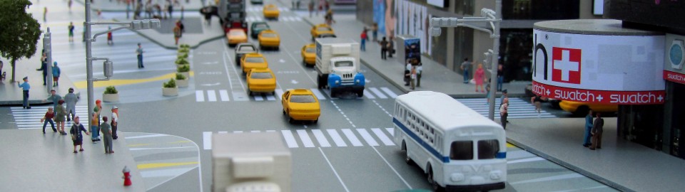
Category Archives: Model Making Process

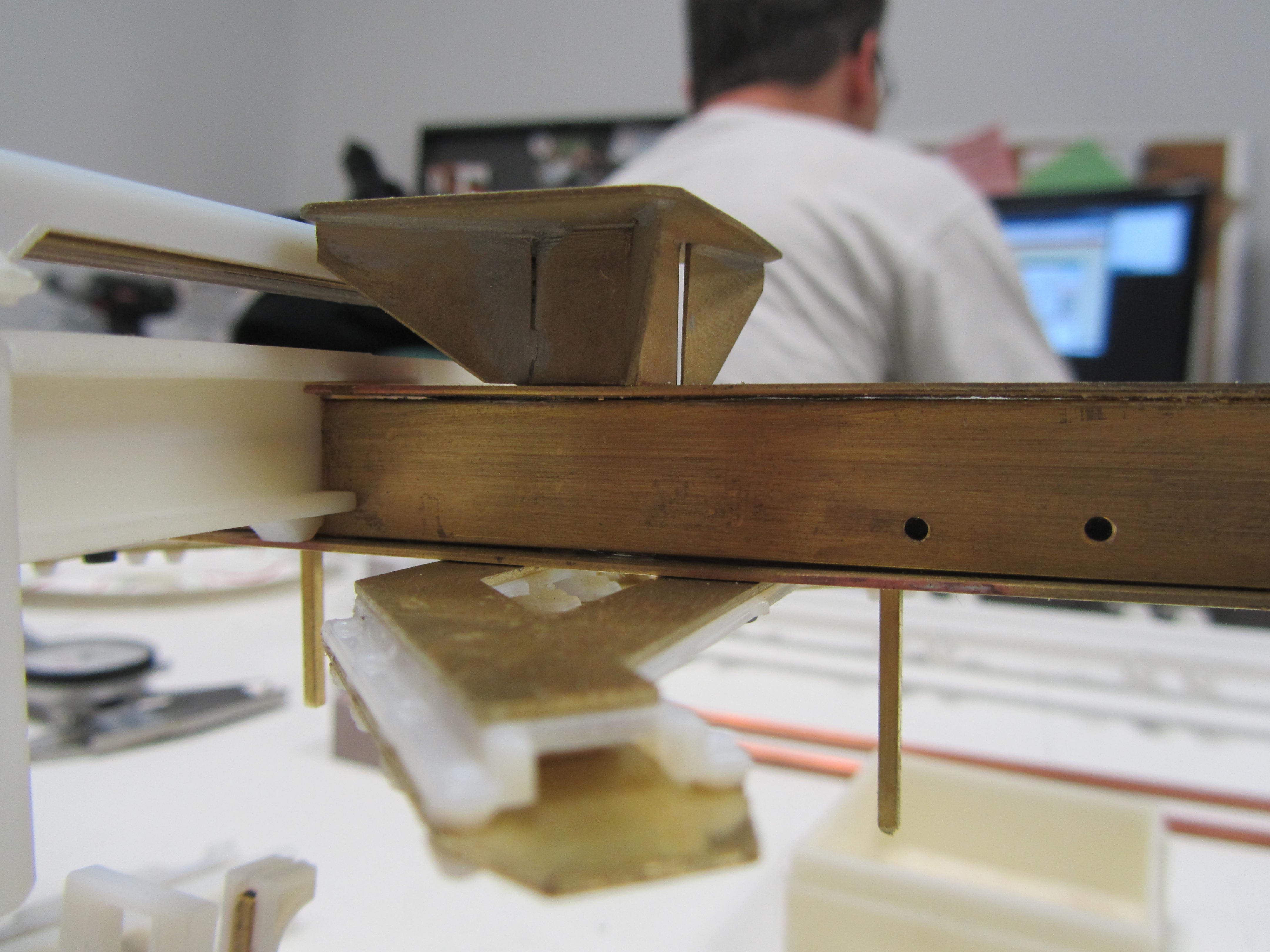
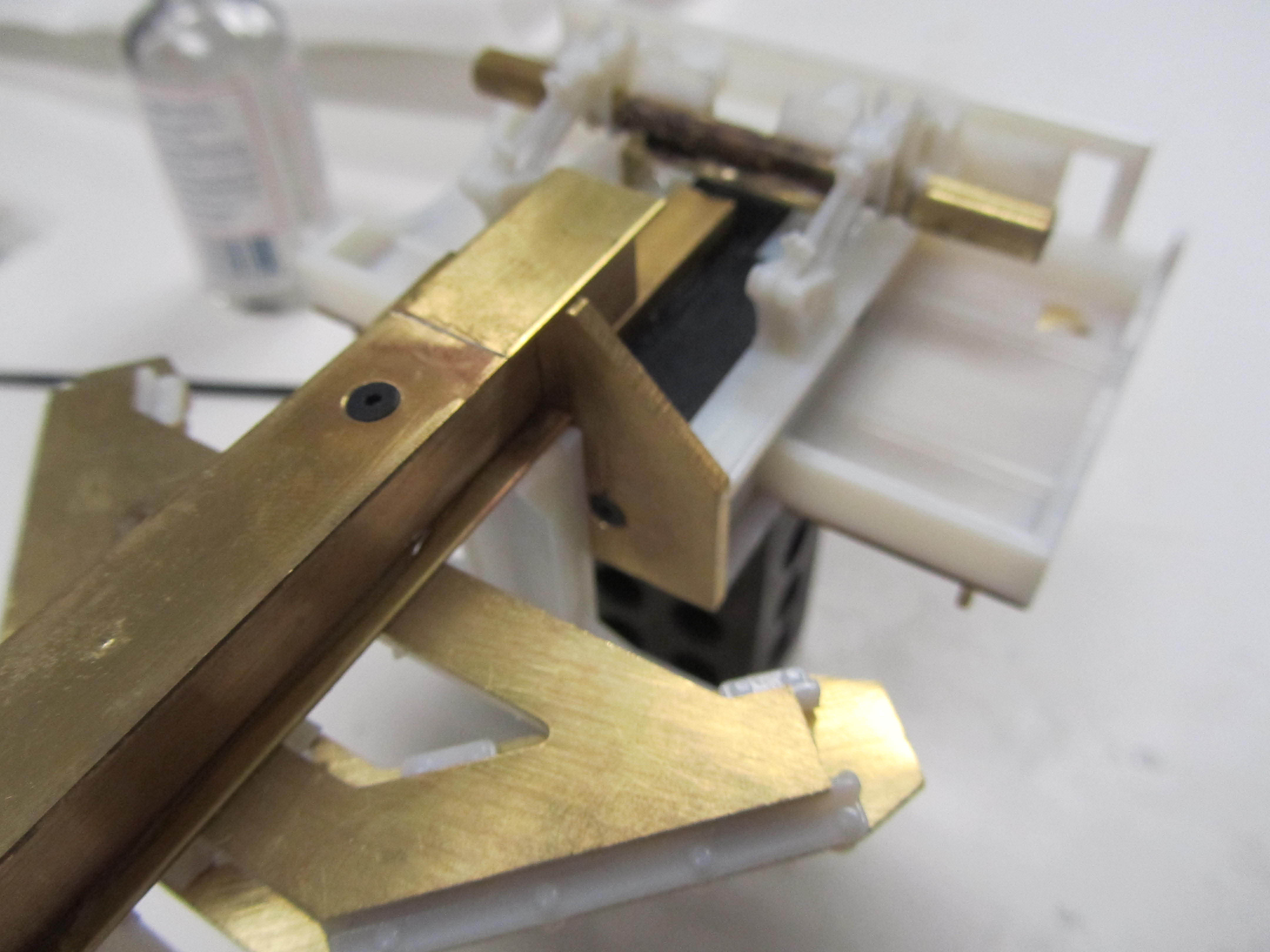
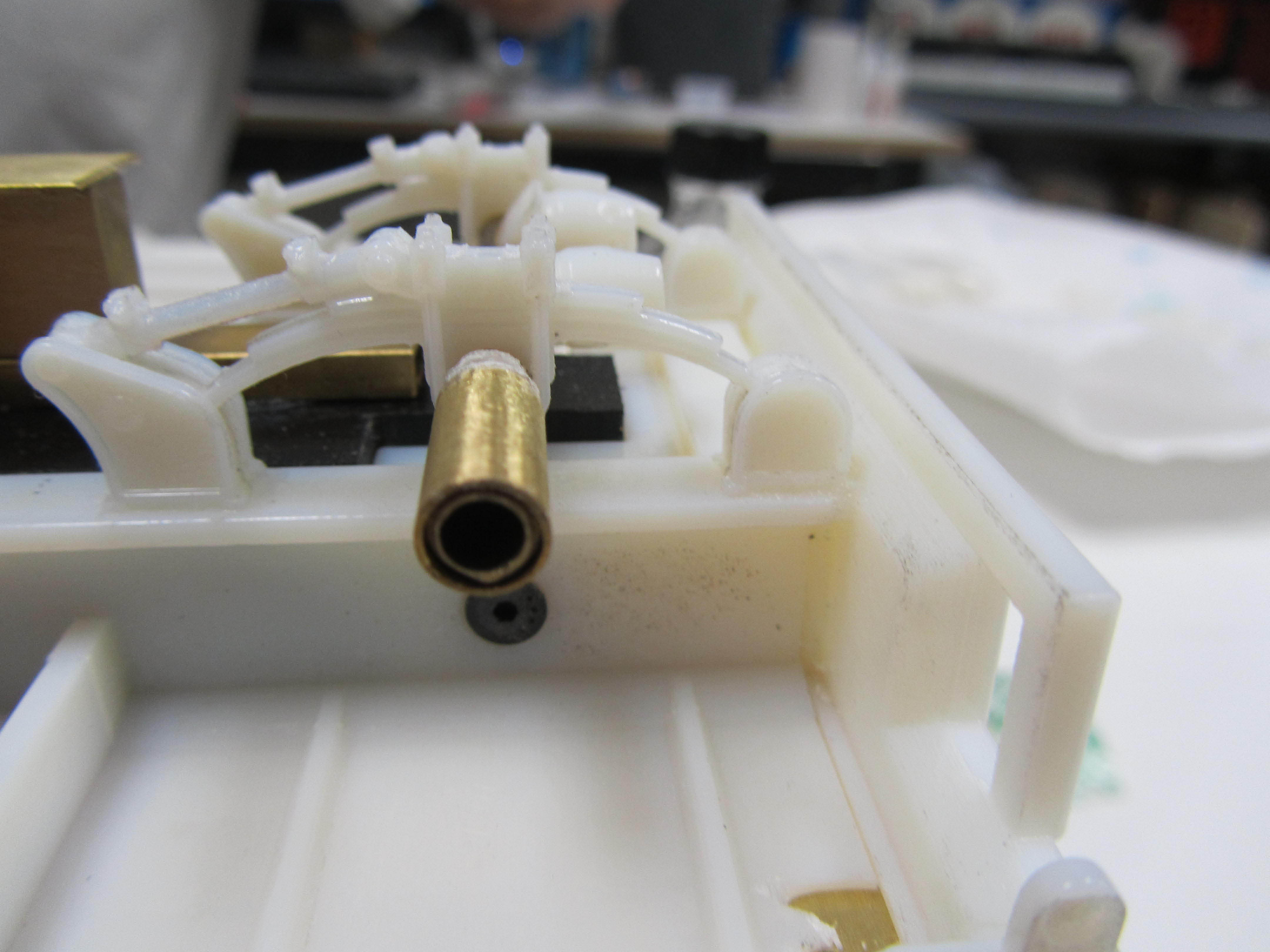
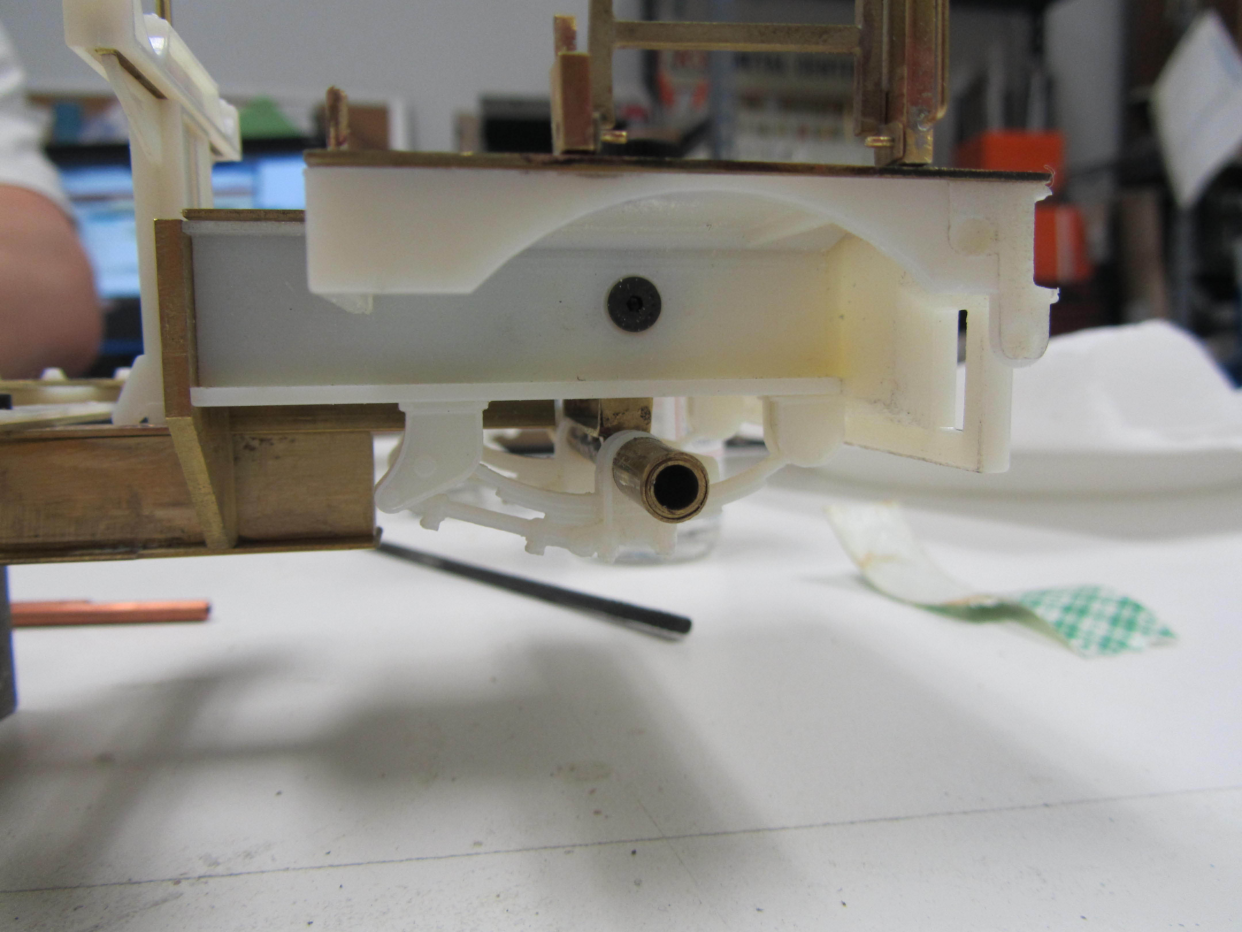
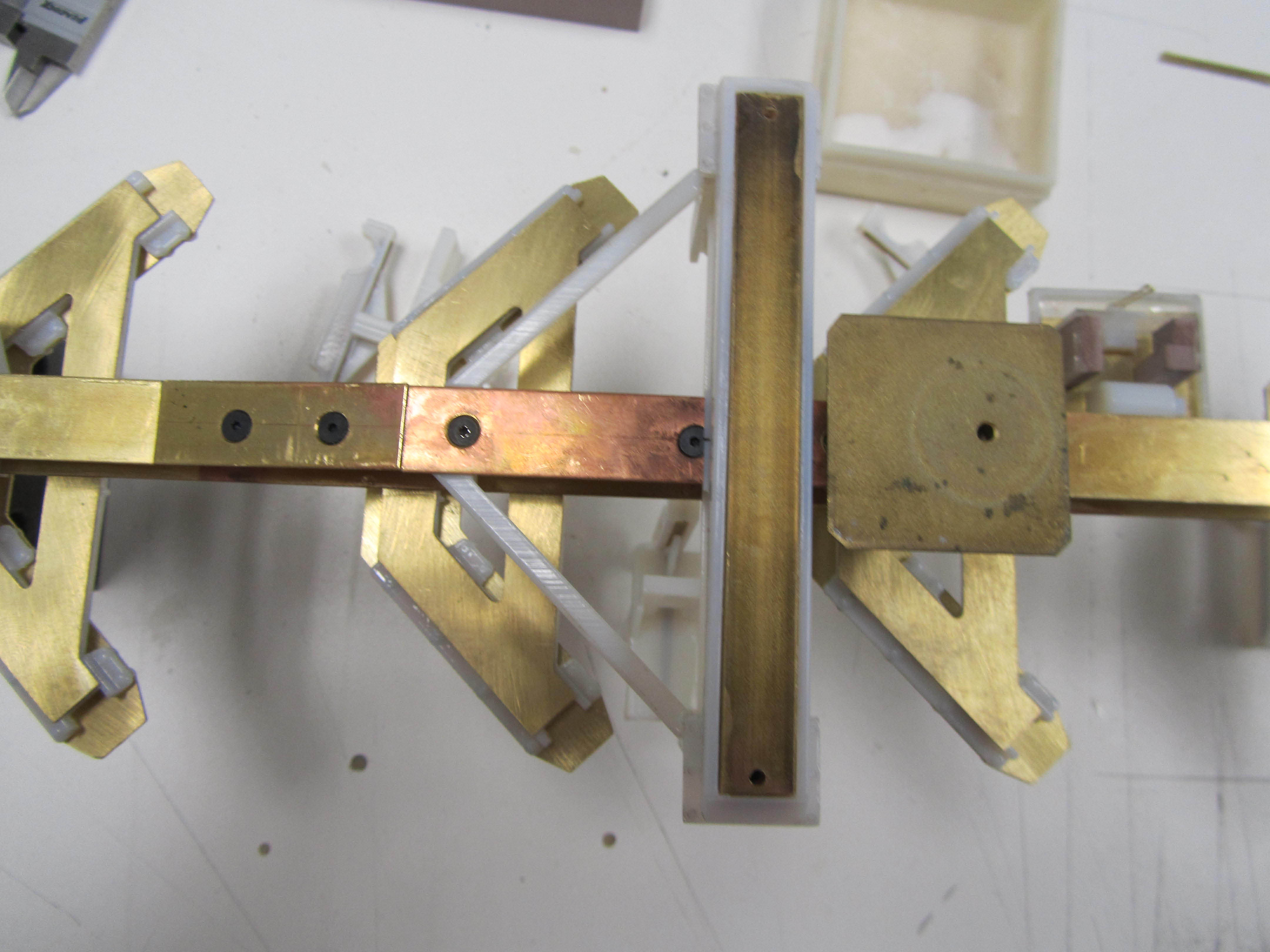
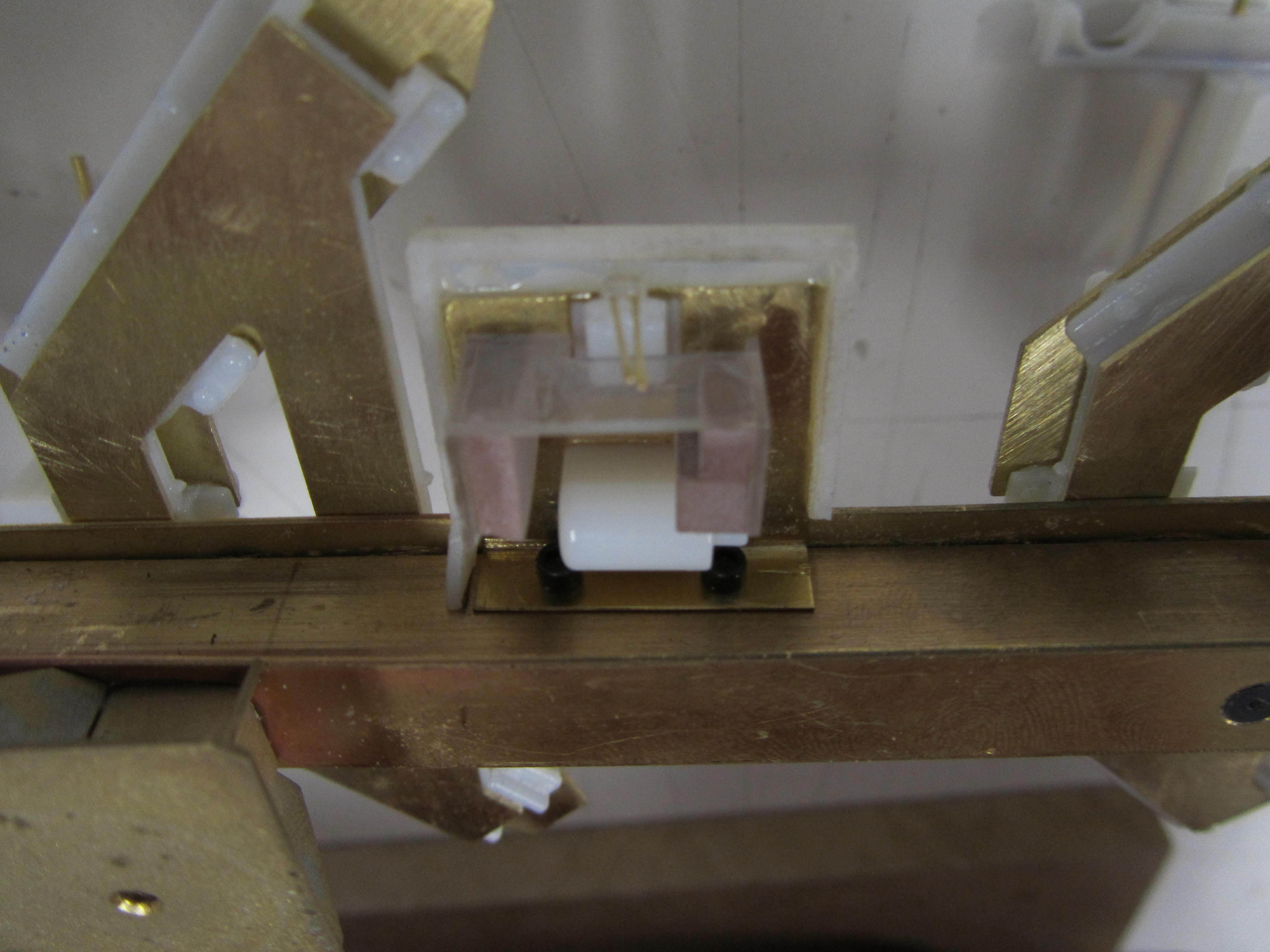
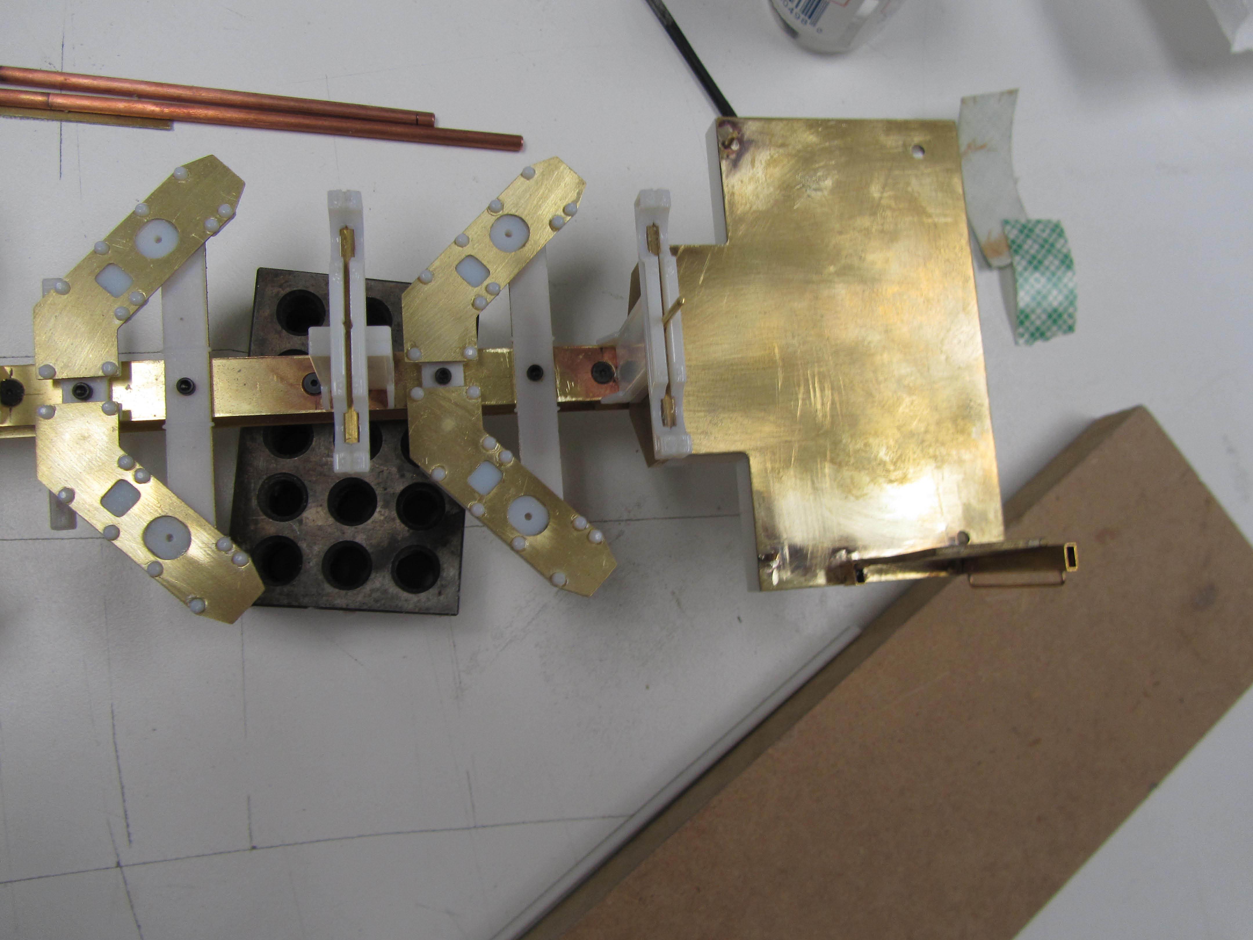
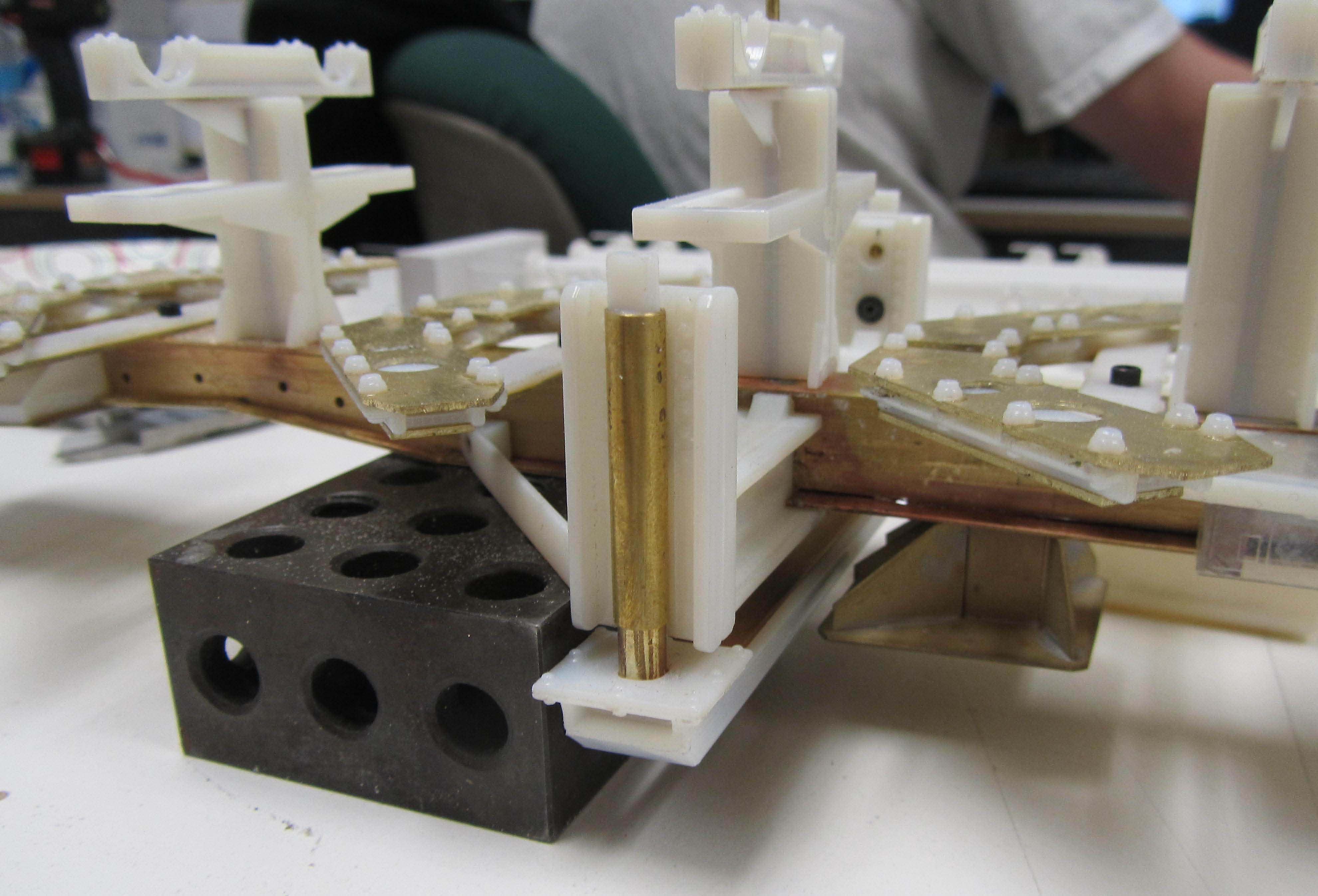
A Different Approach to the Same Truck Model
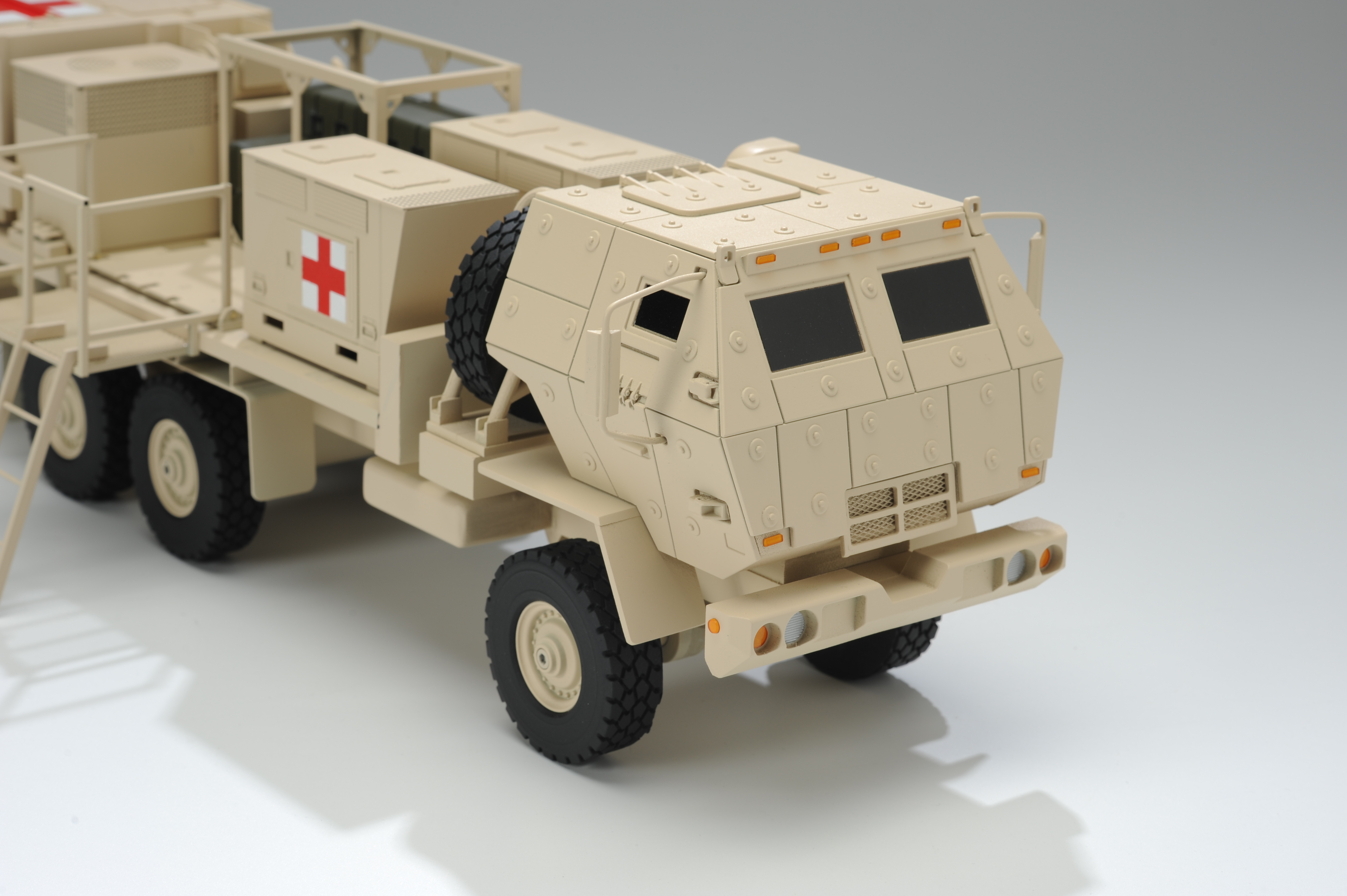
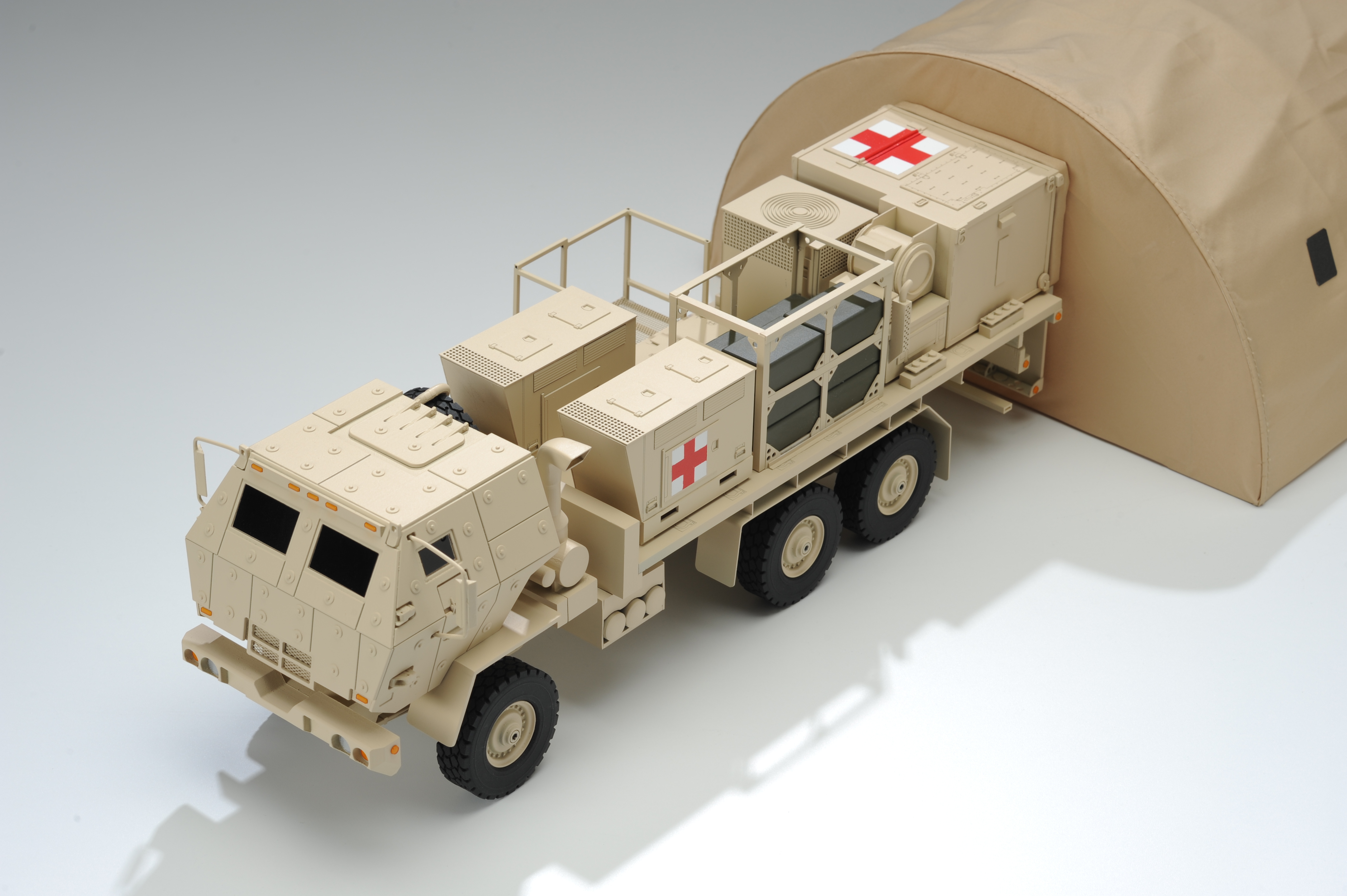
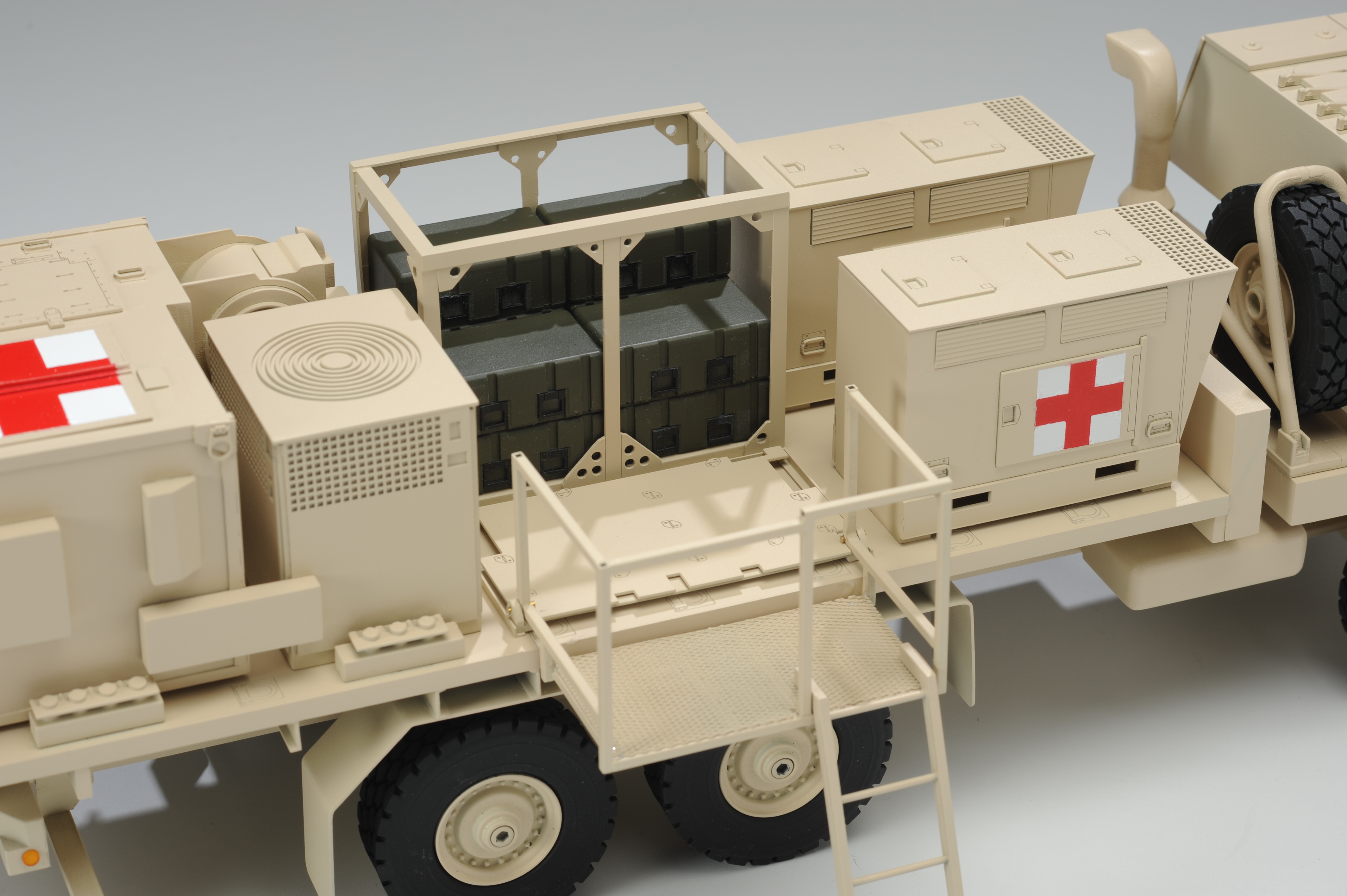
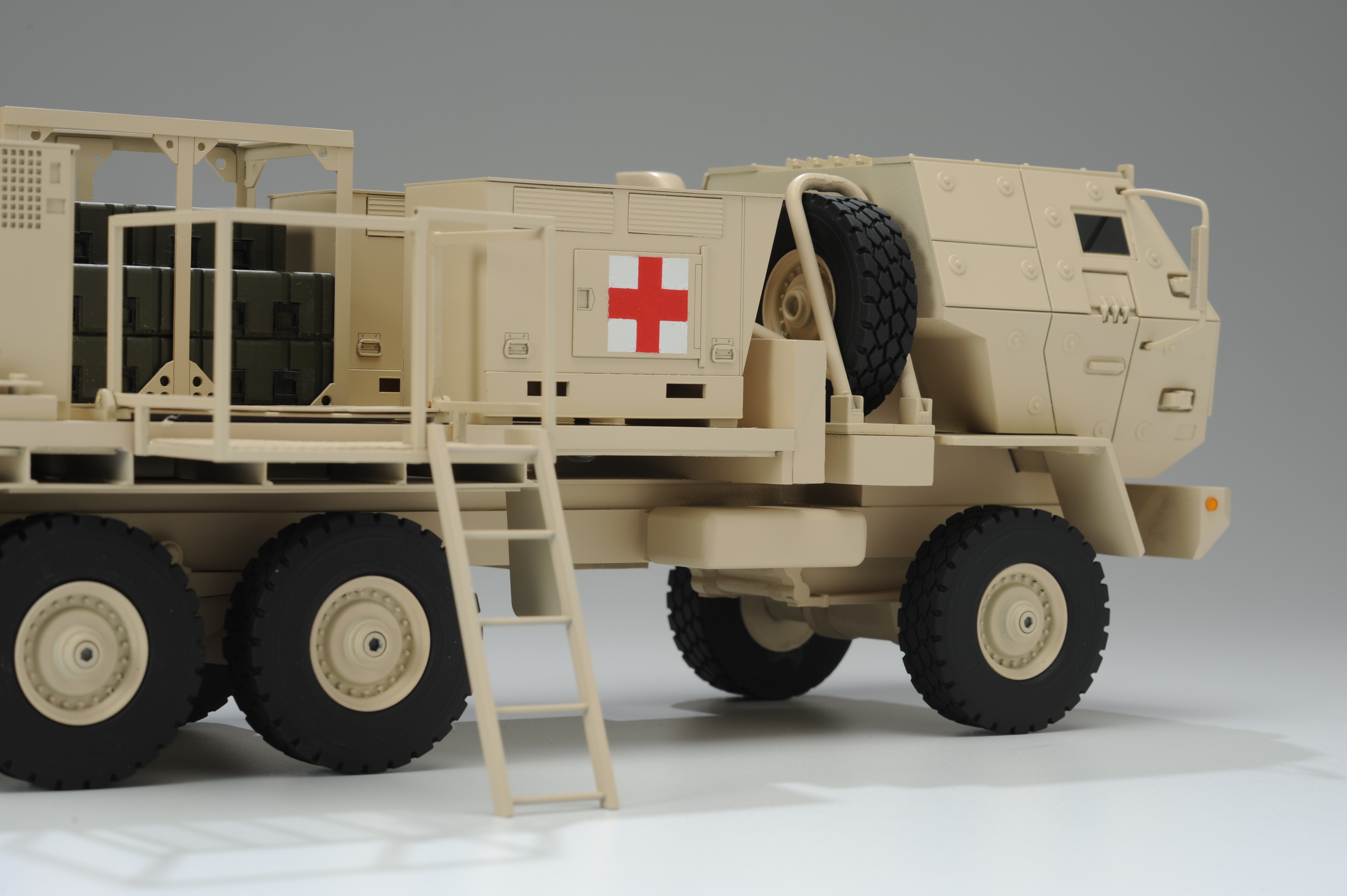
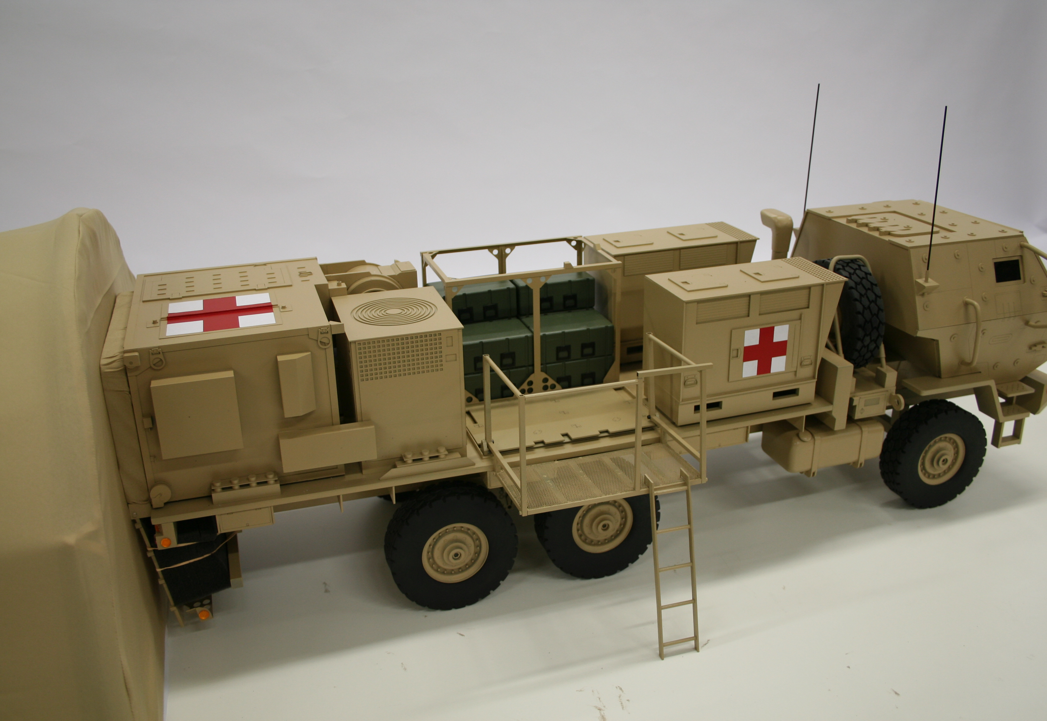
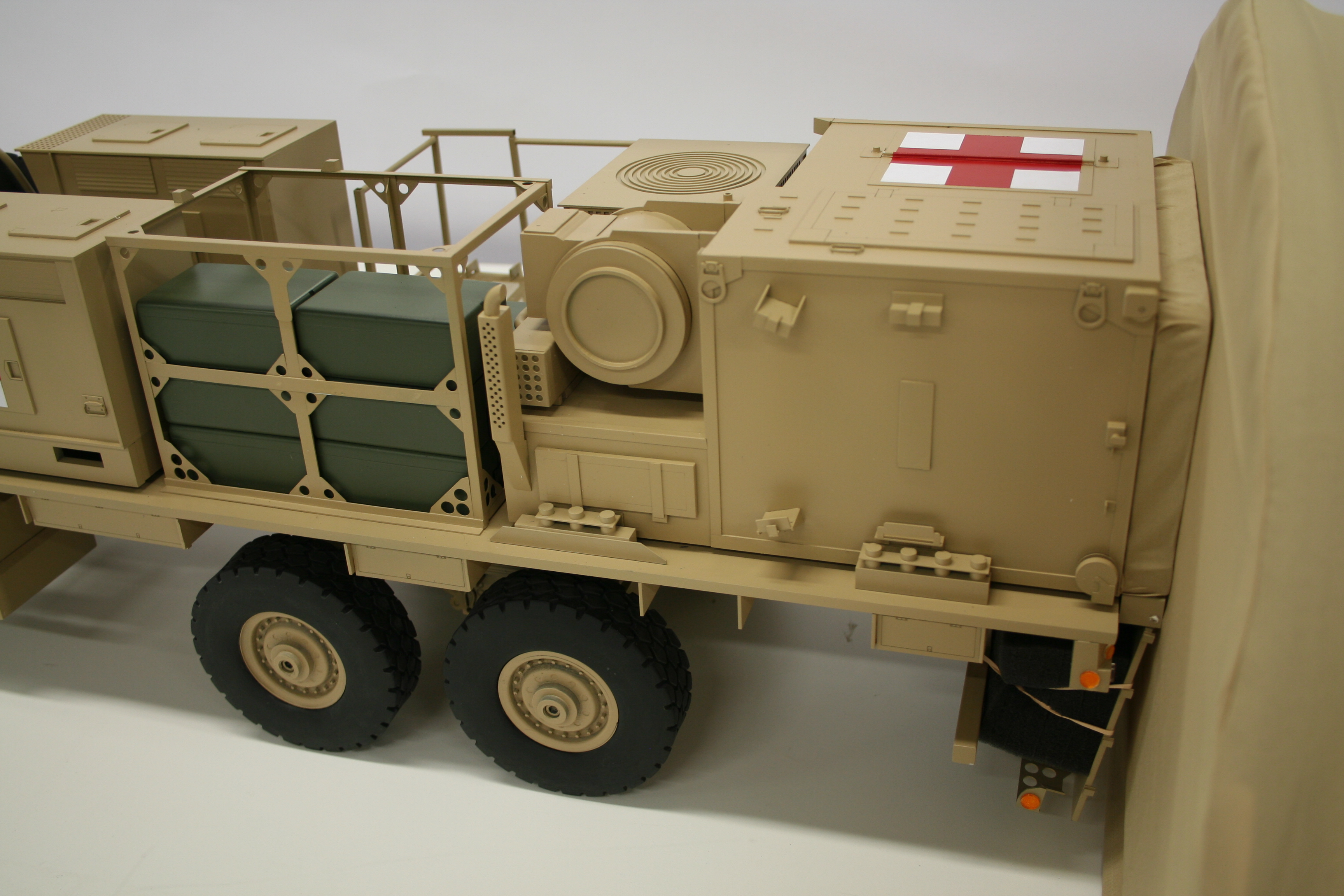
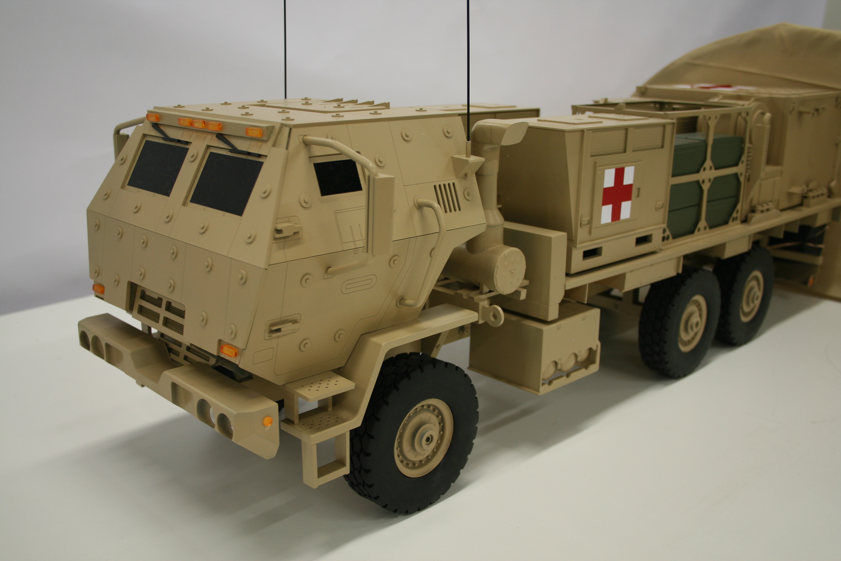
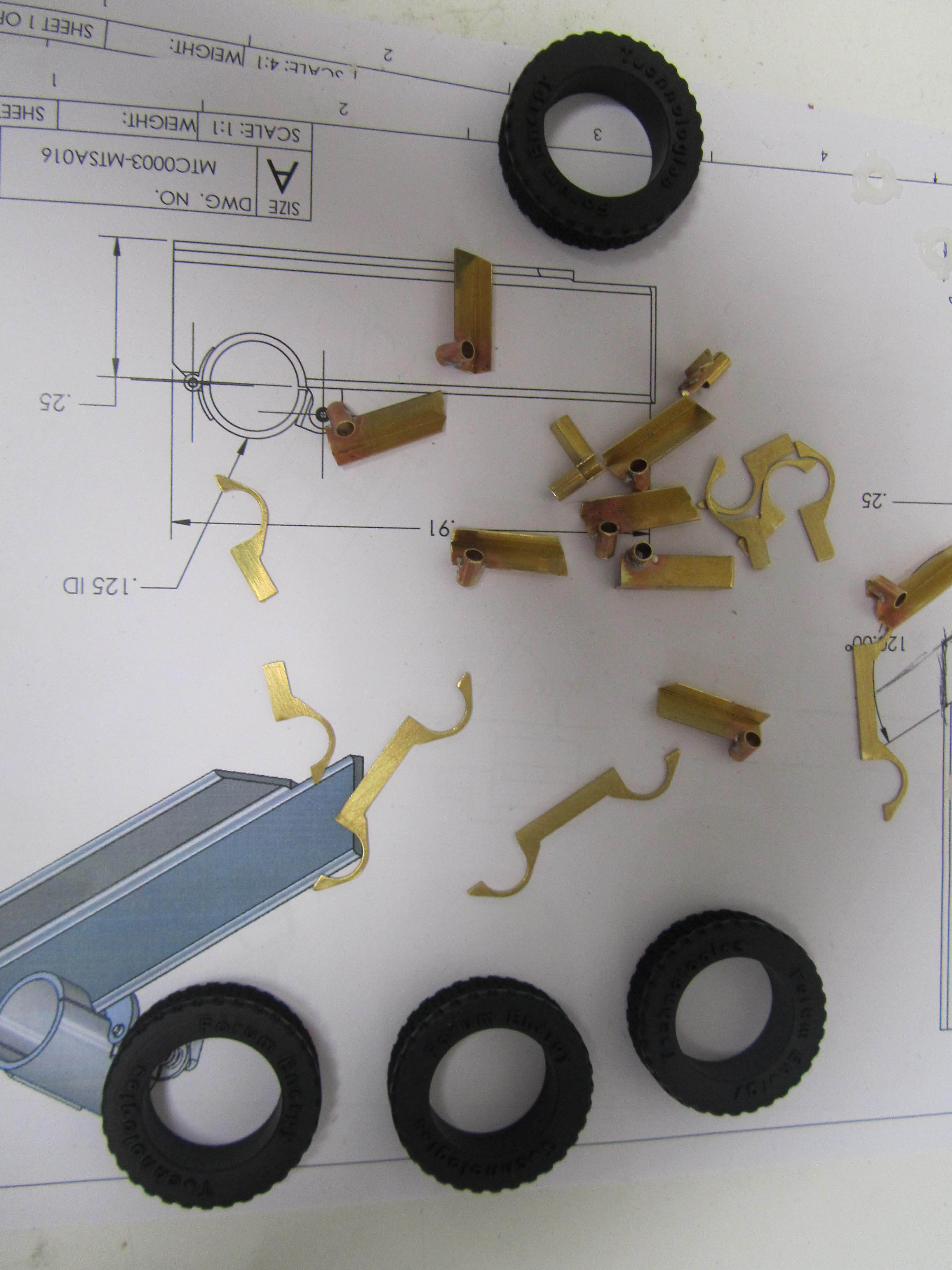
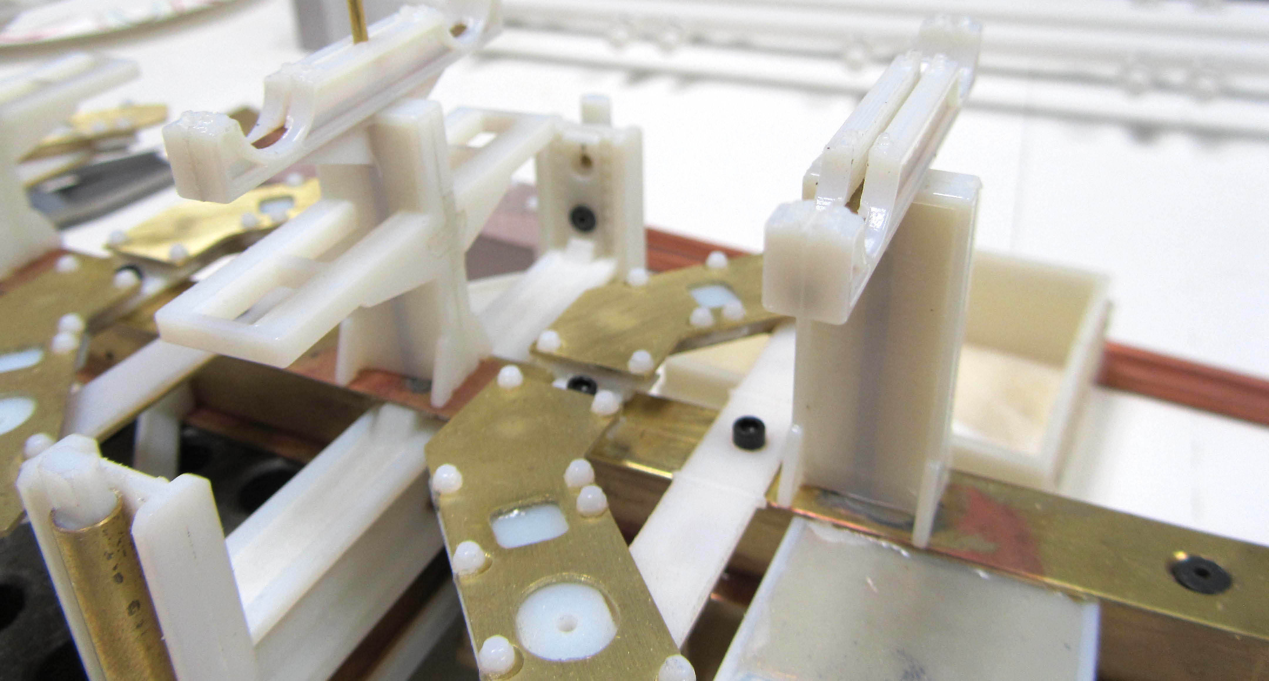
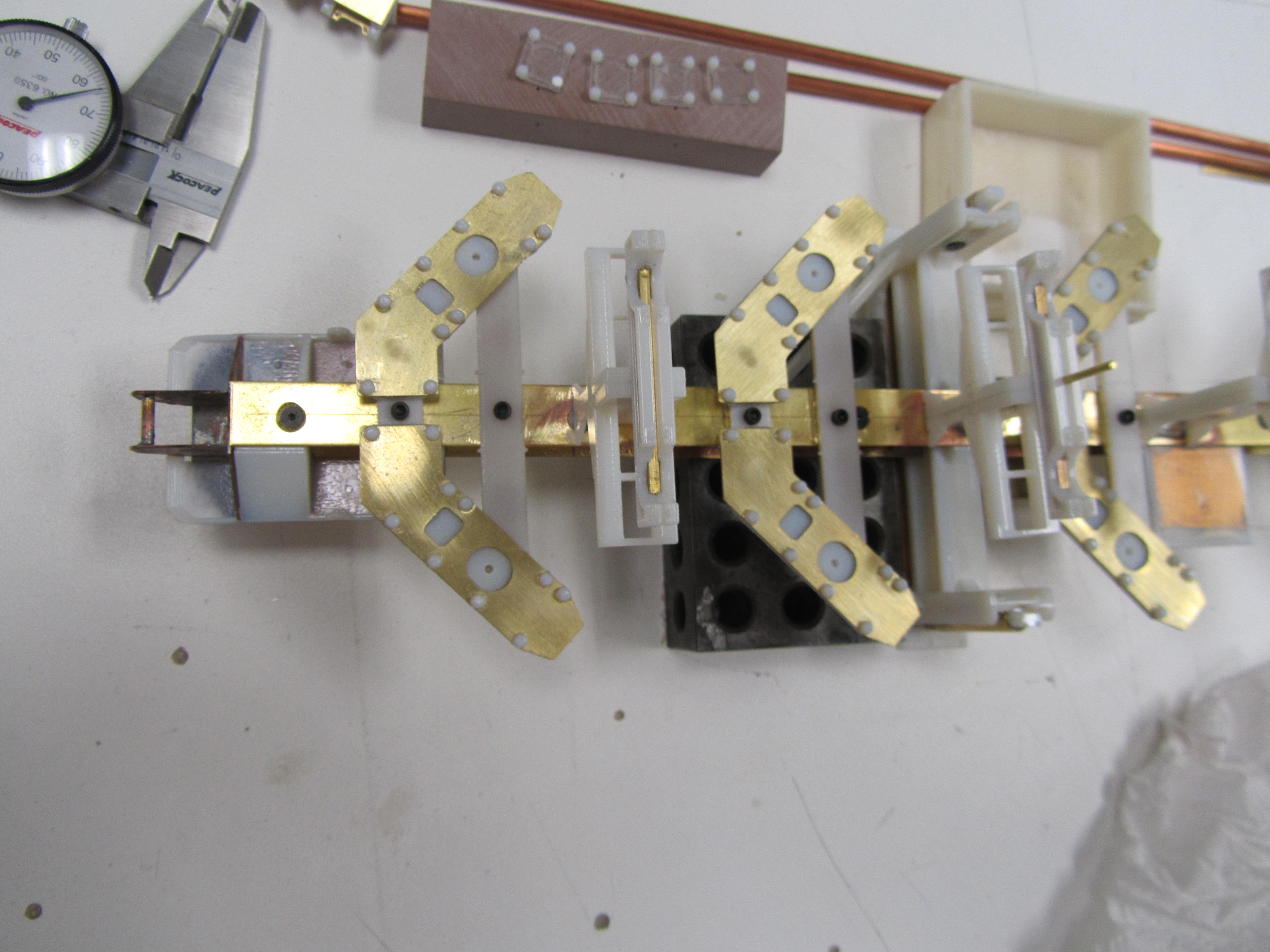
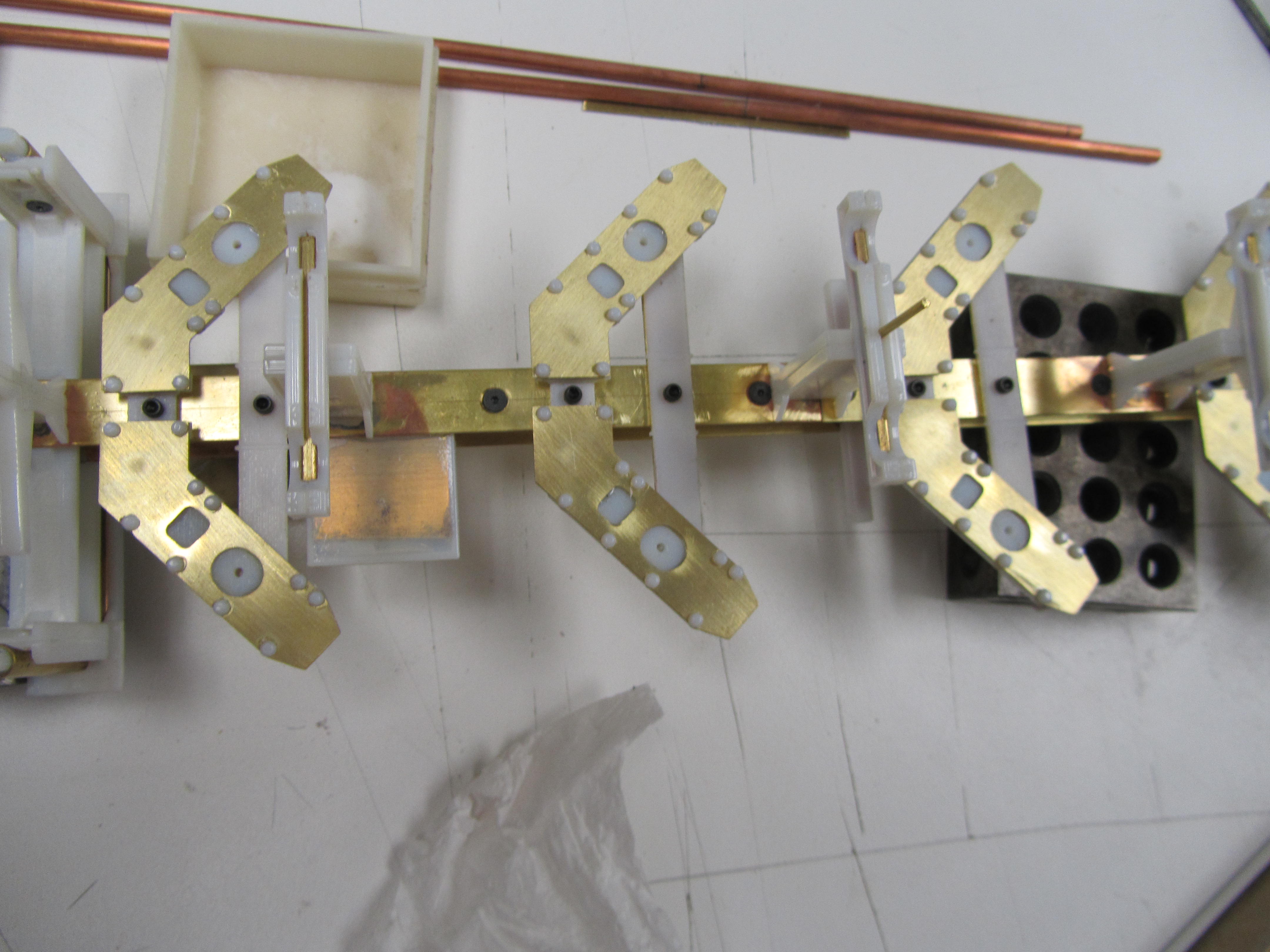
Nearly two years ago, KiwiMill built a model of a five ton FMTV armored cab truck model with a specialized medical hospital payload. The model was 1/10th scale with the truck about 36″ long. It was completely hand-built for trade show use, with a brass frame and numerous brass details. The cab had separately applied bolt head and hinge details on laser etched acrylic armor panels.


Recently the model shop was asked to make a second FMTV truck, in 1/20th scale. Having acquired a 3D printer during the interim, KiwiMill approached the build somewhat differently the second time around. Many detailed parts that were built by hand originally, were drawn on the computer and made with the Objet 3D printer, precisely and quickly. Soldered brass was still used for strength and longevity. The fabric tent design was altered a bit as well.


There is no one right way to make a scale model. Approaches vary depending on the materials and fabrication methods available, as well as the particular preferences of the model maker. Specific client requests may factor in, and of course, budget and time constraints. Skilled model makers adapt and adjust to new technology, continuously honing and improving on their techniques.
Something that doesn’t change in the profession: the purpose of the scale model will always drive the fabrication method and materials used, while the quality of the finished product will determine if the chosen methods were successful.
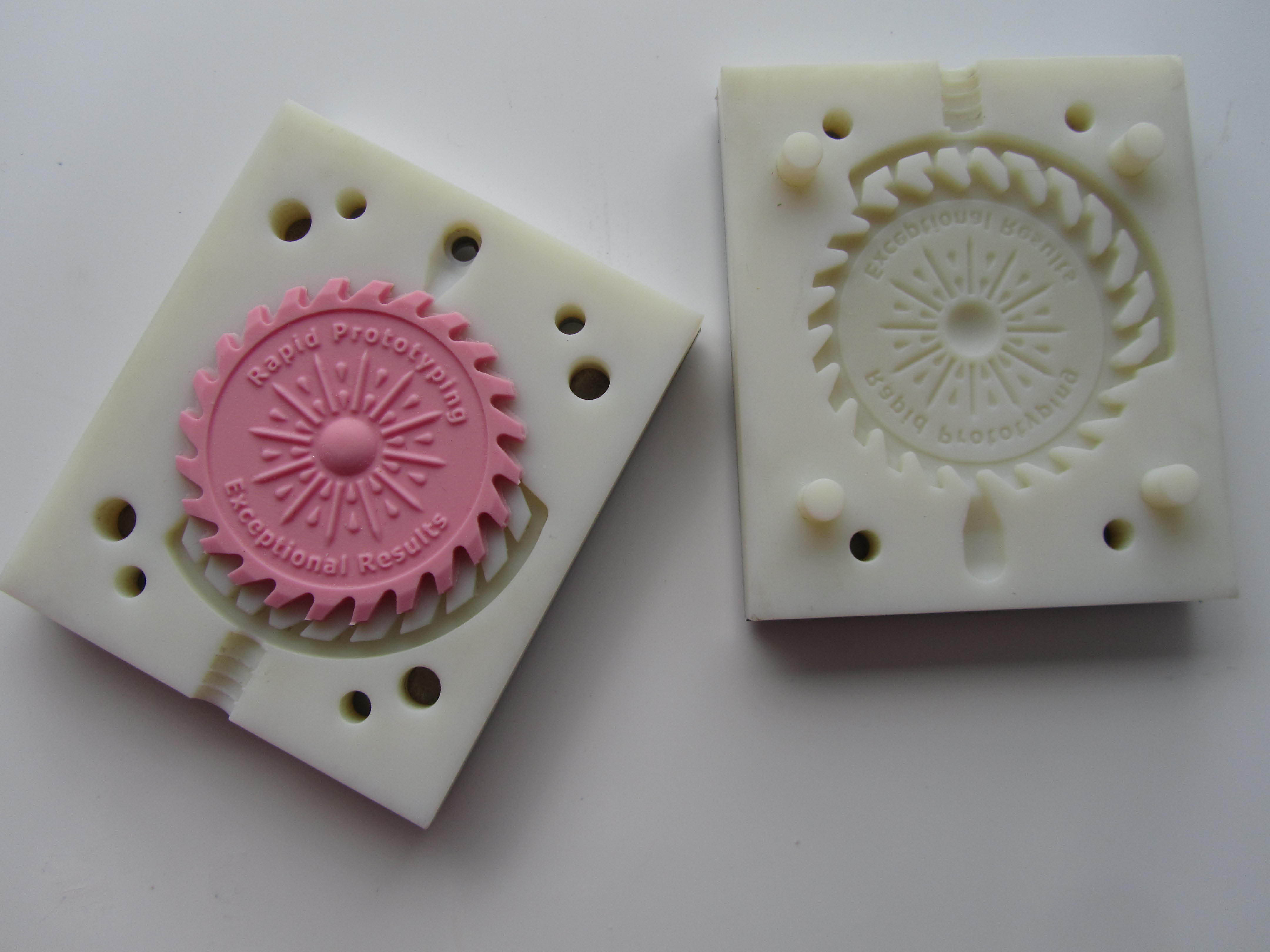
3D Printed Mold for Casting
KiwiMill has an Objet 3D printer to make scale model parts efficiently, accurately and with greater detail.
When the printer is not in use for model parts, it’s available to customers for rapid prototyping services. Not only can the printer create parts with very quick turn around and accuracy, but it can be used to create a tool for molding and casting multiple pieces.
Here is a 3D printed mold created by our designer, Mike, that will be used to cast multiple parts. It incorporates gating and venting in the design.


Creating a mold using a 3D printer saves time. Traditional molds require a Master to first be created, and then the mold is made from this initial part. 3D printing the mold means there is no need for a Master. The mold is created with a 3D drawing, then “grown” in the 3D printer. It comes out ready to cast its first part. In this sense, 3D printing the mold eliminates entirely the molding step as it is traditionally known.


Once you have your 3D printed mold, different materials can be cast in it – from very rigid, to soft and flexible.
Yet another technology tool for Model Makers to make use of, and for our customers to take advantage of.
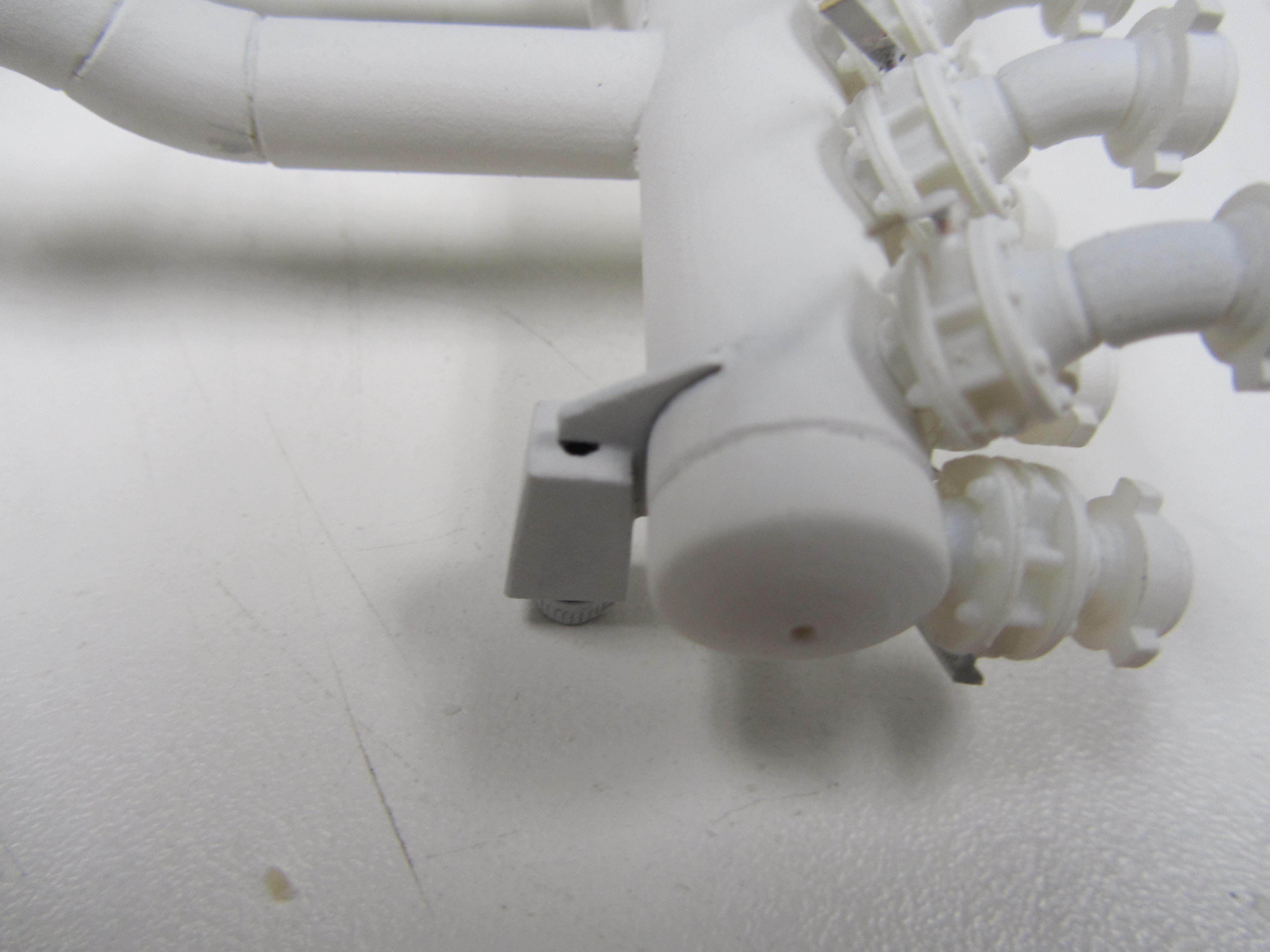
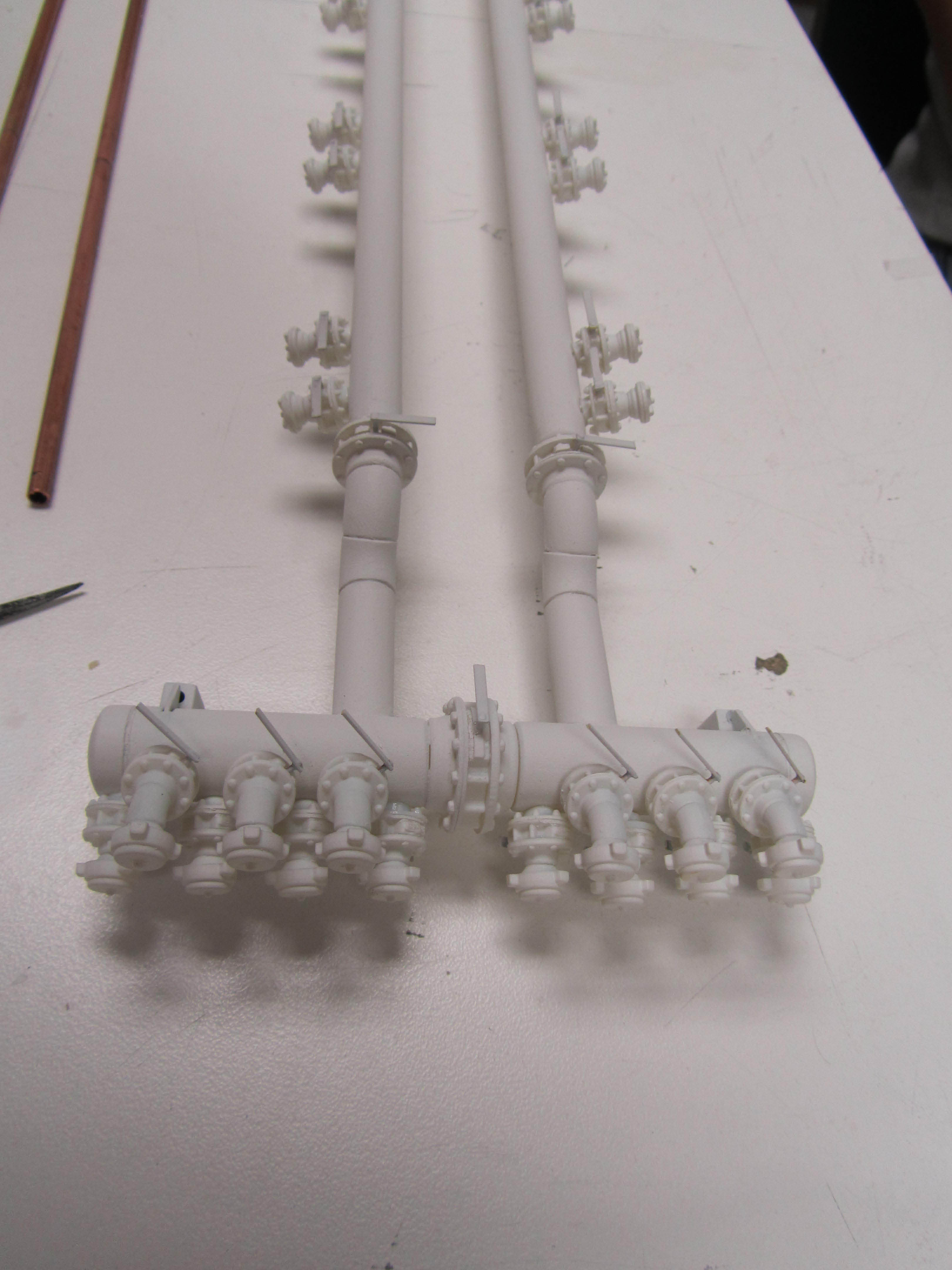
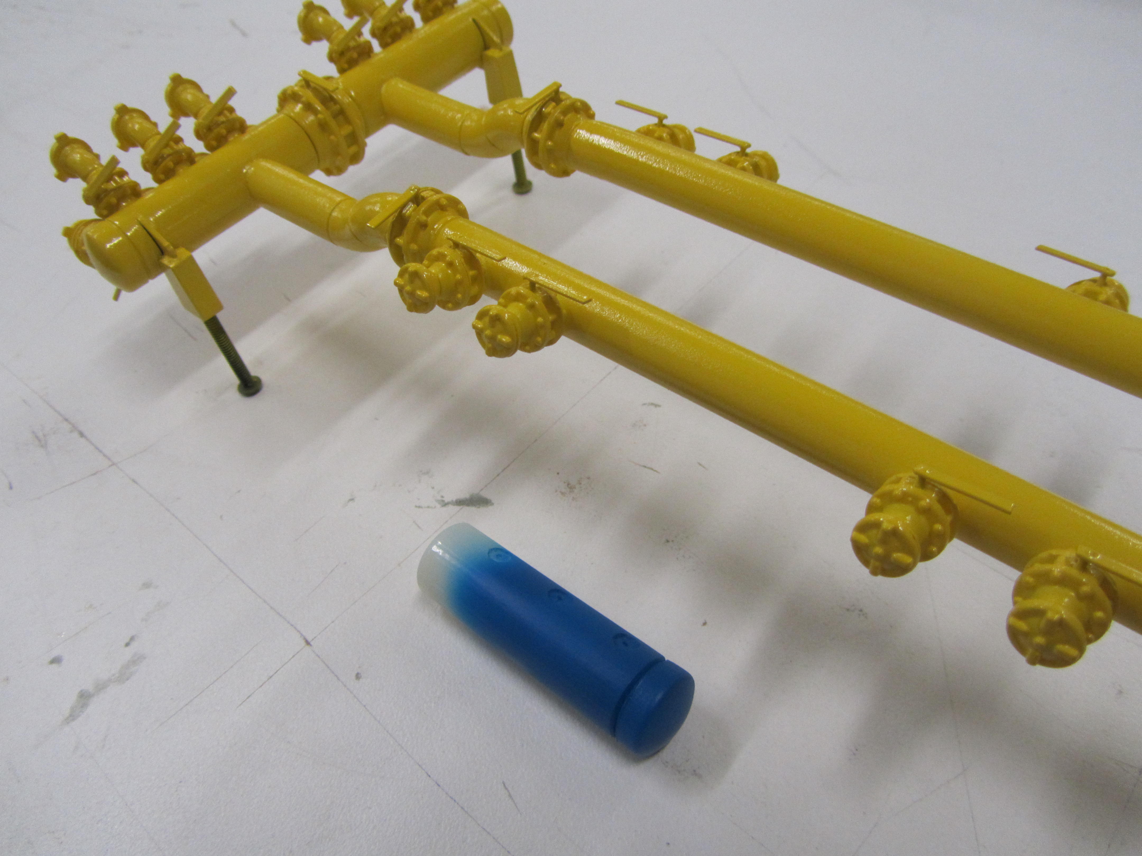
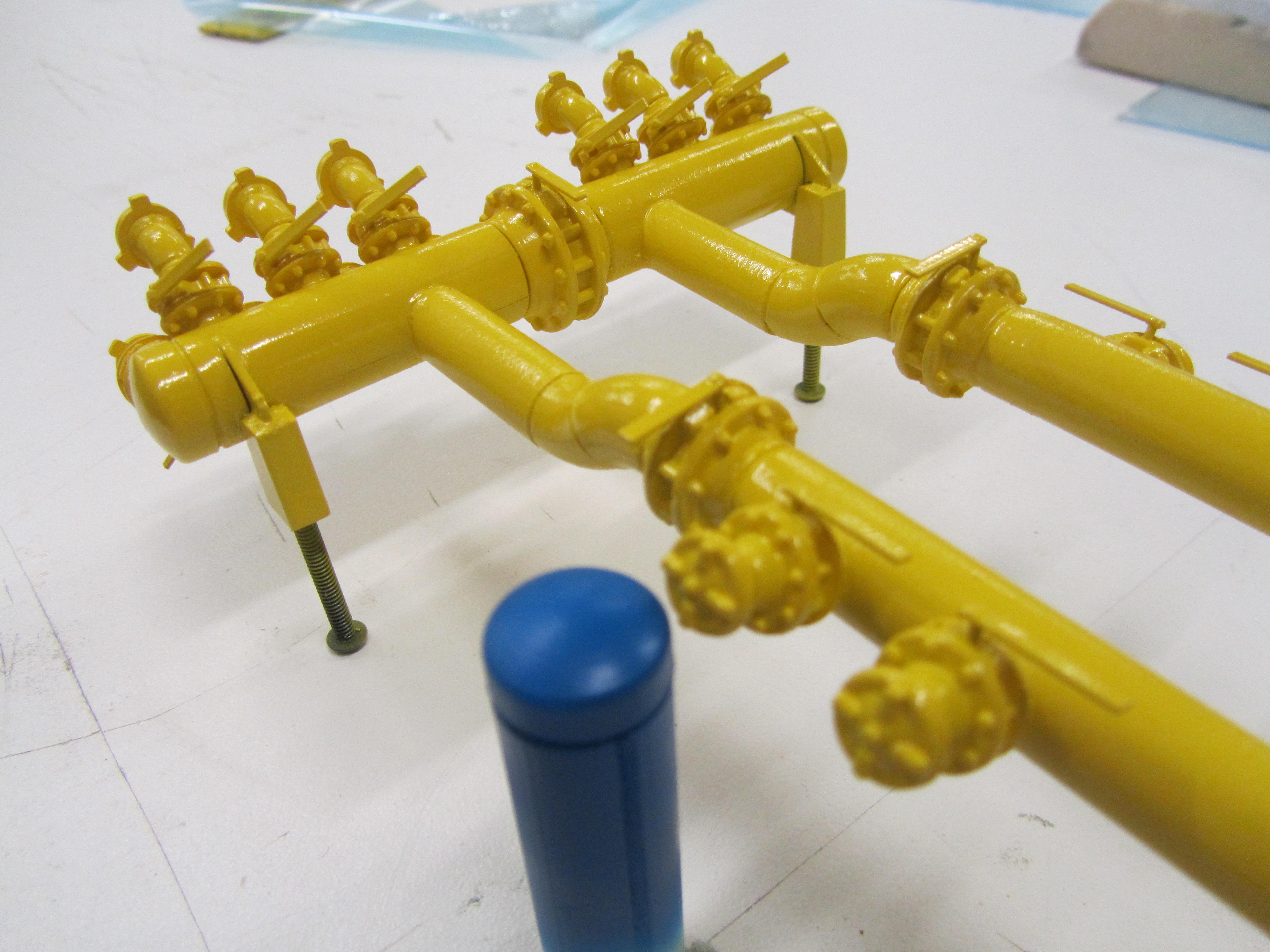
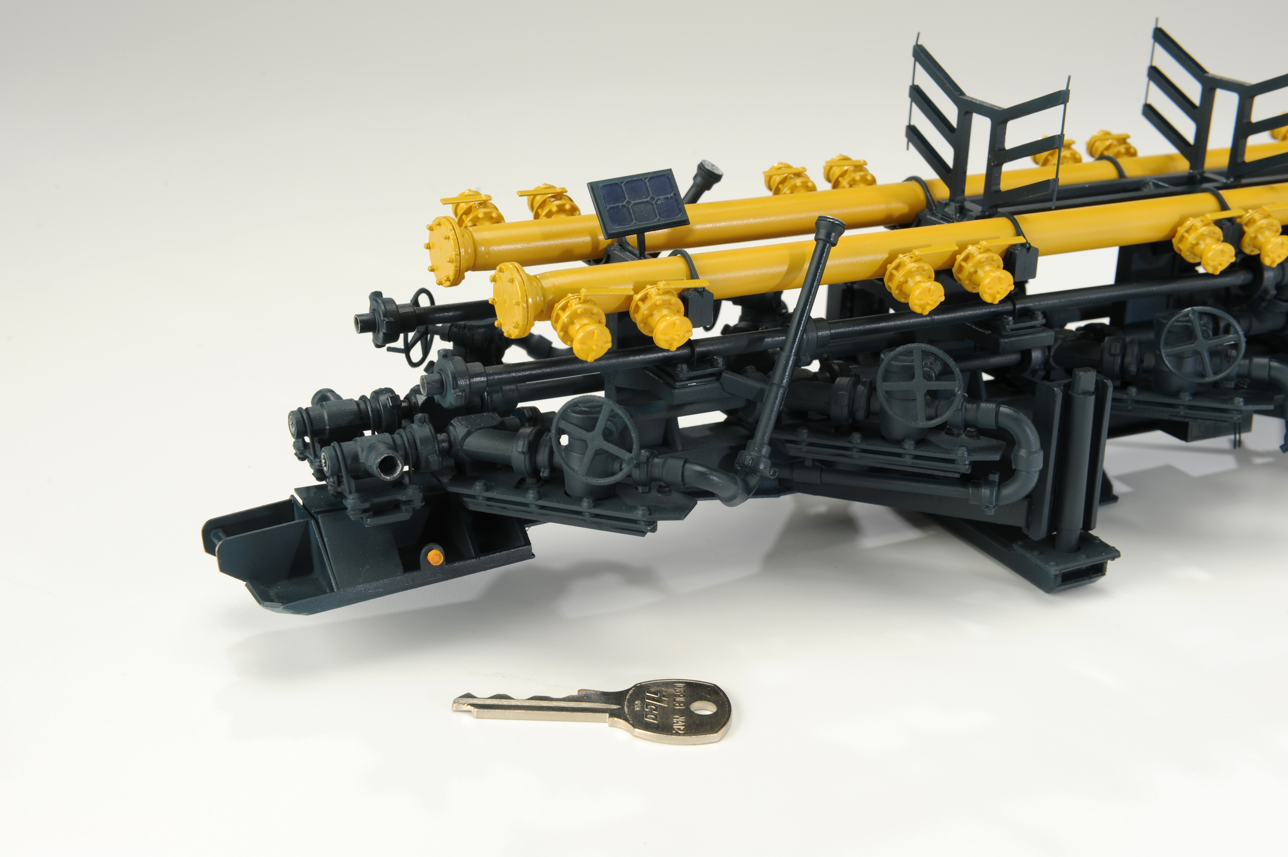
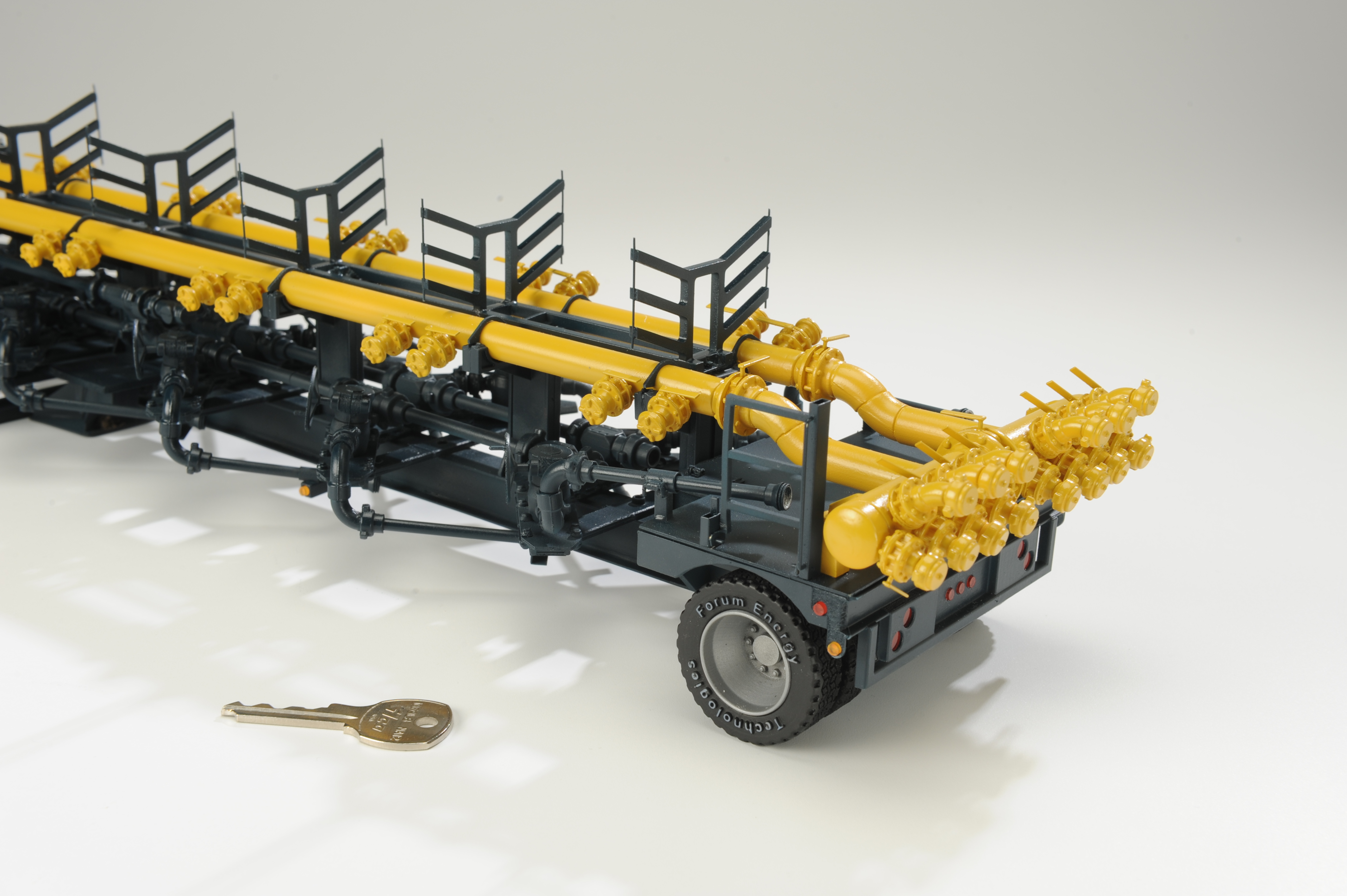
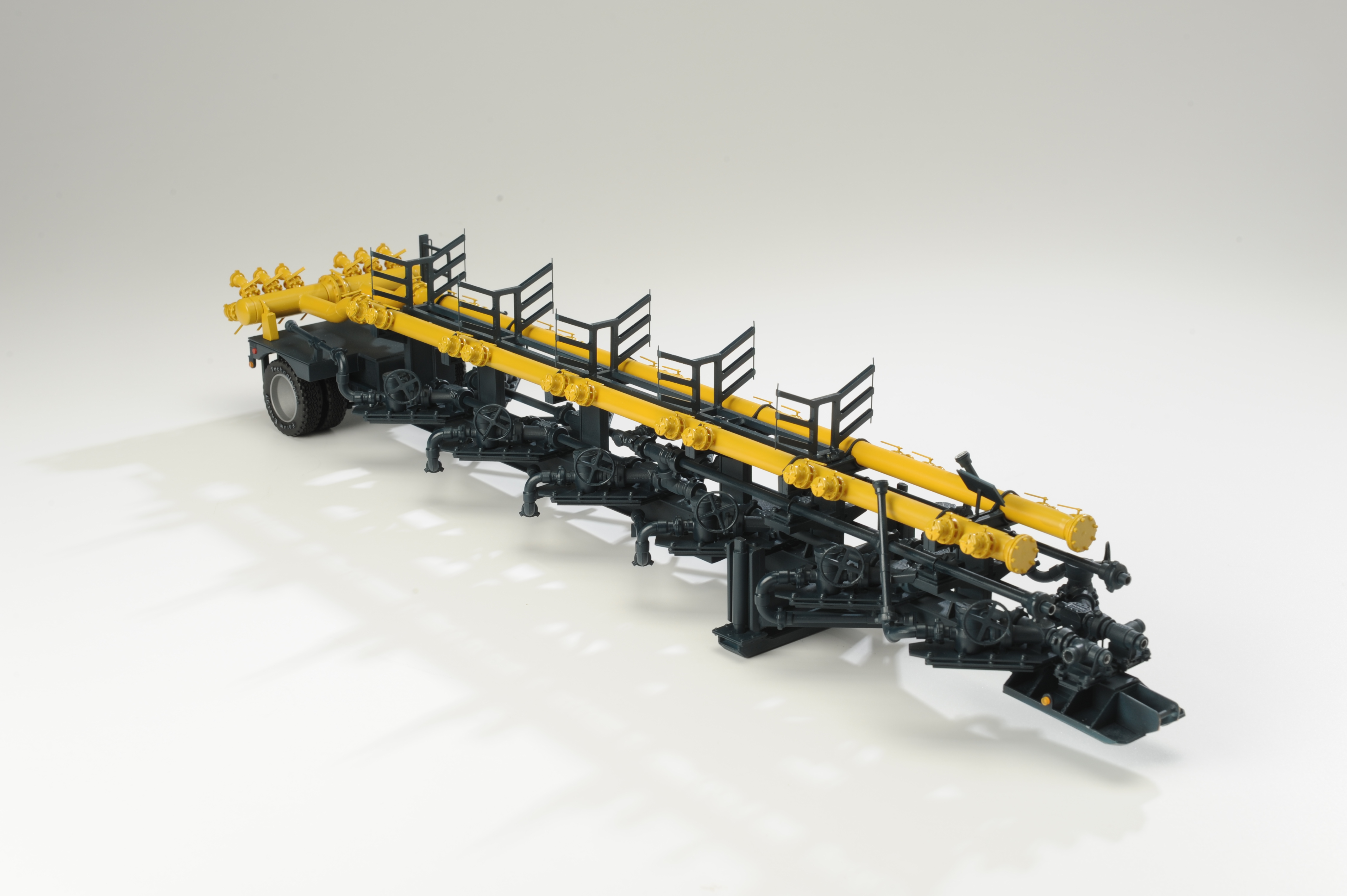
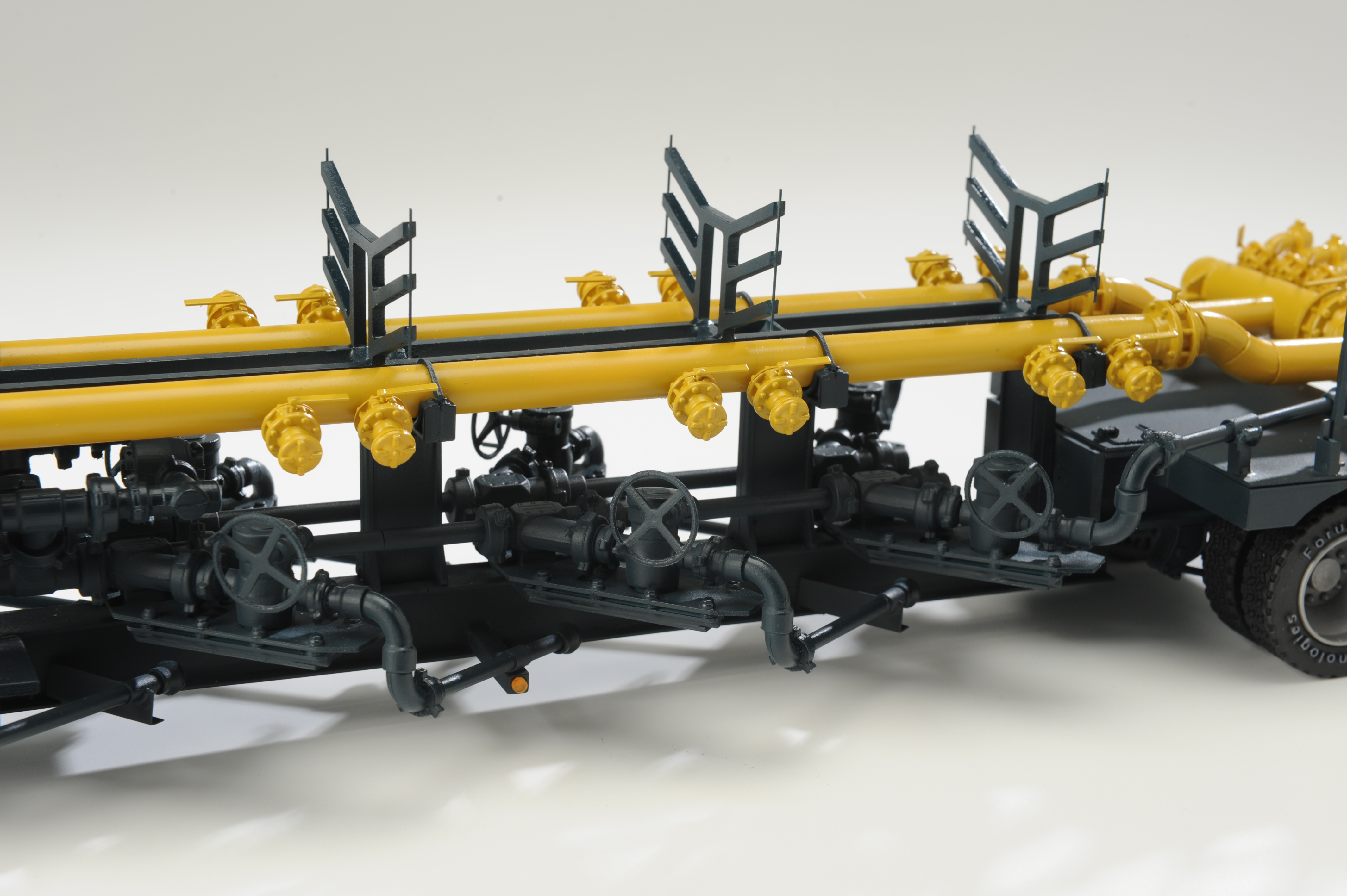
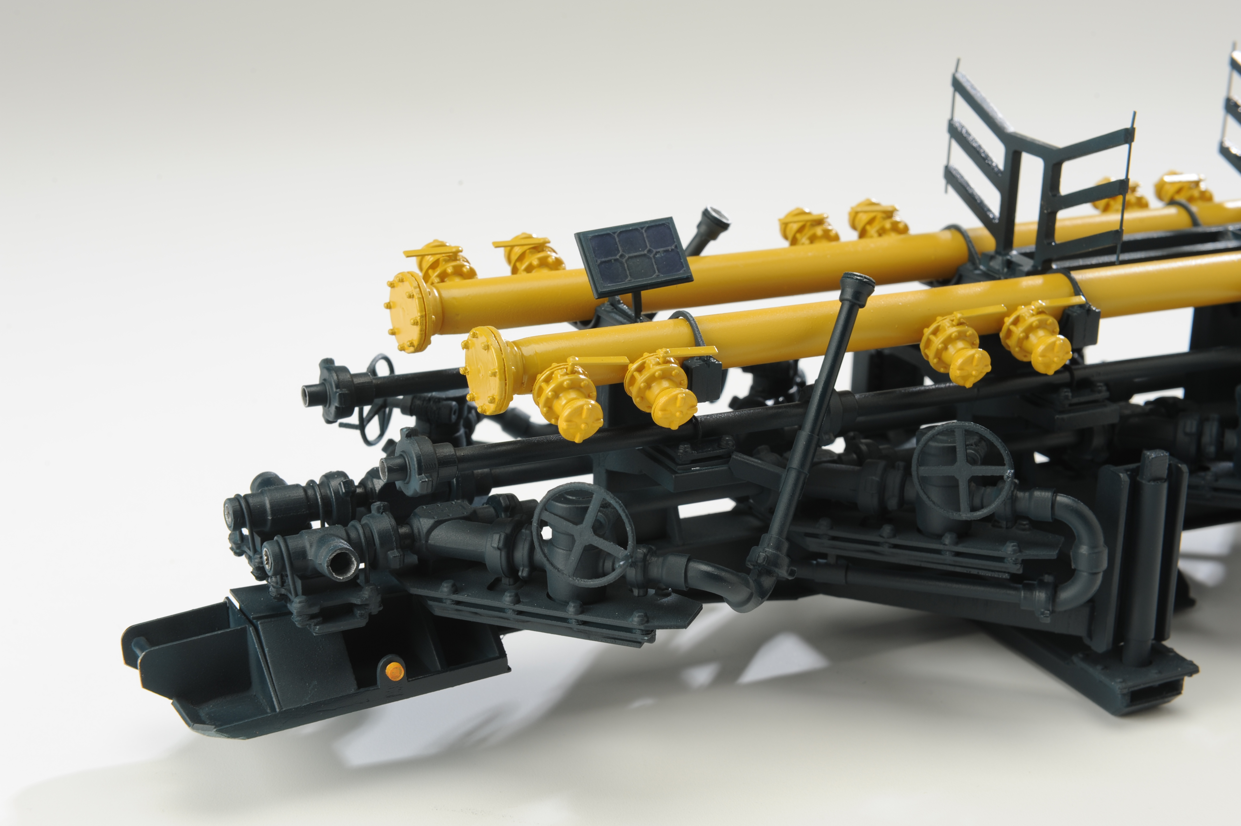
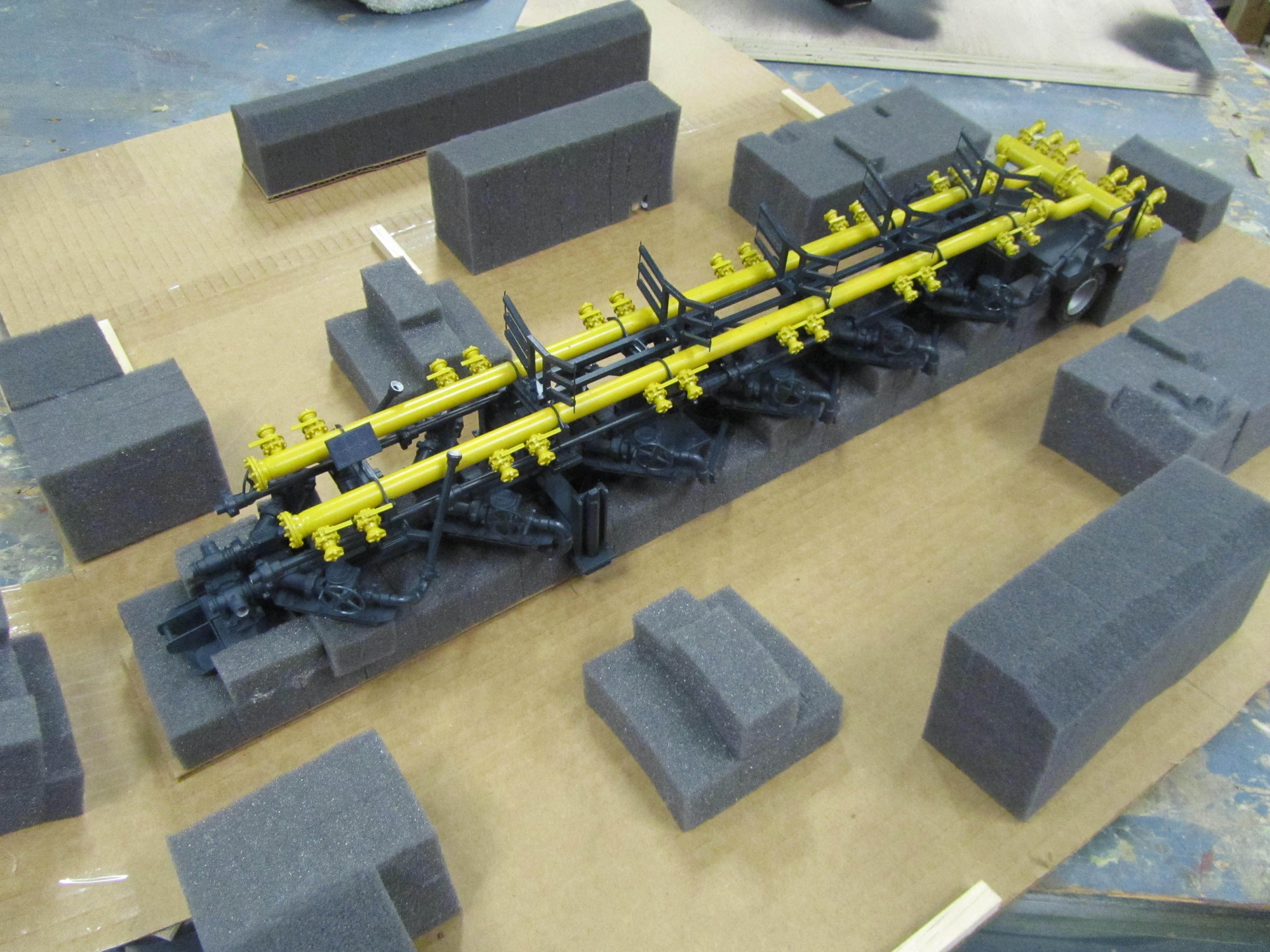
Intricate Build of Manifold Trailer Industrial Model
This industrial model of a Manifold Trailer for Forum Energy Technologies involved extensive use of our 3D printer. The result was stunning detail, accuracy, and with the addition of brass structure, great strength.
KiwiMill model makers were very pleased with this attempt to create a model primarily of 3D printed parts that were then assembled into the finished product.


T

Creating Wooded Areas on a Site Model

Ever wonder how to make wooded areas on a small-scale site model? After much experimentation over the years, KiwiMill settled on a method that captures the essence of this particular landscape. Interestingly, it does not involve planting hundreds of individual model trees close together. No matter how tightly placed the trees, this method still lets in too much light – not realistic looking for a densely wooded area.

Instead, industrial filters – the kind used in air conditioning units – form the base for the wooded areas. These filters are then hand-sculpted by the model makers. Depending on the over-all scale of the model, these sculpted pieces are layered on top of each other. Three layers of 1/2 inch thick filters represent 60 ft high trees accurately.


The layers are painted all over the surfaces with glue and flocked with various natural shades of green, brown and yellow. When placed on a site model they represent small-scale wooded areas with depth and lushness.


Is a 3D Printer Like Having an Extra Model Maker?

The model maker team here at KiwiMill is definitely pleased with the addition of our newest Objet 3D printer. While we jokingly refer to it as our extra employee – it is quite a miraculous technology – it’s worth noting the support systems needed to make it run, as well as its inherent limitations.
First comes the training necessary to operate, clean and maintain the printer itself. An initial inservice with the sales tech after purchase is a good starting point. Ongoing tech support provided by the manufacturer keeps things running smoothly in the long-term.
Material to run the 3D printer is a regular investment as well. The resin itself is expensive, and to a lesser degree, the support material used to print each item. The resin is the actual plastic that a part is made out of, the support material is what fills in the empty spaces in the design as it prints layer by layer on the tray.
The human labor involved in 3D printing is perhaps the most interesting aspect of this particular fabrication technique. Three dimensional printers can give the impression that they take the place of a model maker. After all, they are touted as machines capable of growing parts overnight, sometimes even whole models. How true is this exactly?
Traditionally model makers have sat at work benches, or run machinery, cutting, carving and shaping materials to the specifications needed for a model part. This method is considered subtractive – the model maker must extract from a whole piece of material the parts necessary to assemble the model. This certainly takes time and a considerable amount of skill, rightfully earning the model maker’s status of master crafts person.
Innovations in the field of model making have introduced automated machines that will do the extracting for you. CNC (computer numerical control) machines guide a router, lathe or mill to carve out parts automatically. Three dimensional drawings have been programmed into the machine by a computer, to provide coordinates for the subtracting device. X and Y coordinates guide the machine back and forth and the Z coordinate tells the machine what up and down motions to make, thus creating a 3 dimensional part.
The 3D printer works a bit differently; it takes a 3D drawing and prints it out in 2D layers. What the model maker must first do is take a CAD engineered drawing from the client and make it “water tight”. This means that all lines in the drawing need to be connected, or closed off. If only a 2D drawing is available, the mode maker must be able to draw it up in 3D. If only the original object exists, with no drawing, it can be scanned and made into a 3D drawing.


Why does the printer need a 3D drawings when ultimately it will be printing it in 2D? How the 3D printer works is that it takes a 3D drawing from any drafting program and slices it into 2D cross-sections, printing each slice out, layer by layer and stacking them up into a three-dimensional object. The unique aspect of this method is that it is additive, not subtractive. The part is built up out of nothing, not extracted from an existing piece of material.

Afer the original 3D draft has been prepared by the model maker and sent to the printer, it is true that the machine then grows the parts itself. This is the magical aspect of the process. A model maker can go home for the night while a part is being created. However, once the part is removed from the printer, it is not exactly ready to use. This is where additional labor is necessary to clean the part.

Support material is the substance that takes the place of empty space in a 3D object, where it is needed to hold up the design as it builds upward. It acts as scaffolding for the object being printed. A layer of support material is laid down on the print tray as well, as a foundation, before any part of the actual object starts printing.
When an object is removed from the 3D printer, it is this support material that needs to be cleaned off the part. Depending on the shape or design of a part, it is the removal of support material that takes the majority of labor in the 3D printing process. Water jet spraying, chemical soaking, scraping and digging out support material from intricate pieces takes time and effort. Sometimes there is so much support material covering a part, that it needs to be extracted out of it as if it were a piece of gold embedded in rock. Thus making 3D printing a bit of a subtractive method as well!

Once the part is cleaned, it needs to be primed, painted, and usually assembled with other parts to make a whole model. We don’t often – if ever – print a model in its entirety. The over all complexity and sophistication of most of our scale models demands greater levels of detail. They are nice supplemental parts to have, and free our model makers up to add the human artistry that gives our models their custom look.

A 3D printer does not replace a model maker, as fun as it is to joke around with the notion. The added technology requires our model makers to be better trained in 3D drafting: drawing, reading and fixing 3D computer files. It ‘s another fabrication choice, and hones the critical thinking skills that determine what parts will be printed, CNC machined, hand-built or crafted in yet another method. This blend of artistry, engineering and technology is making the model making field such an exciting place to be right now.
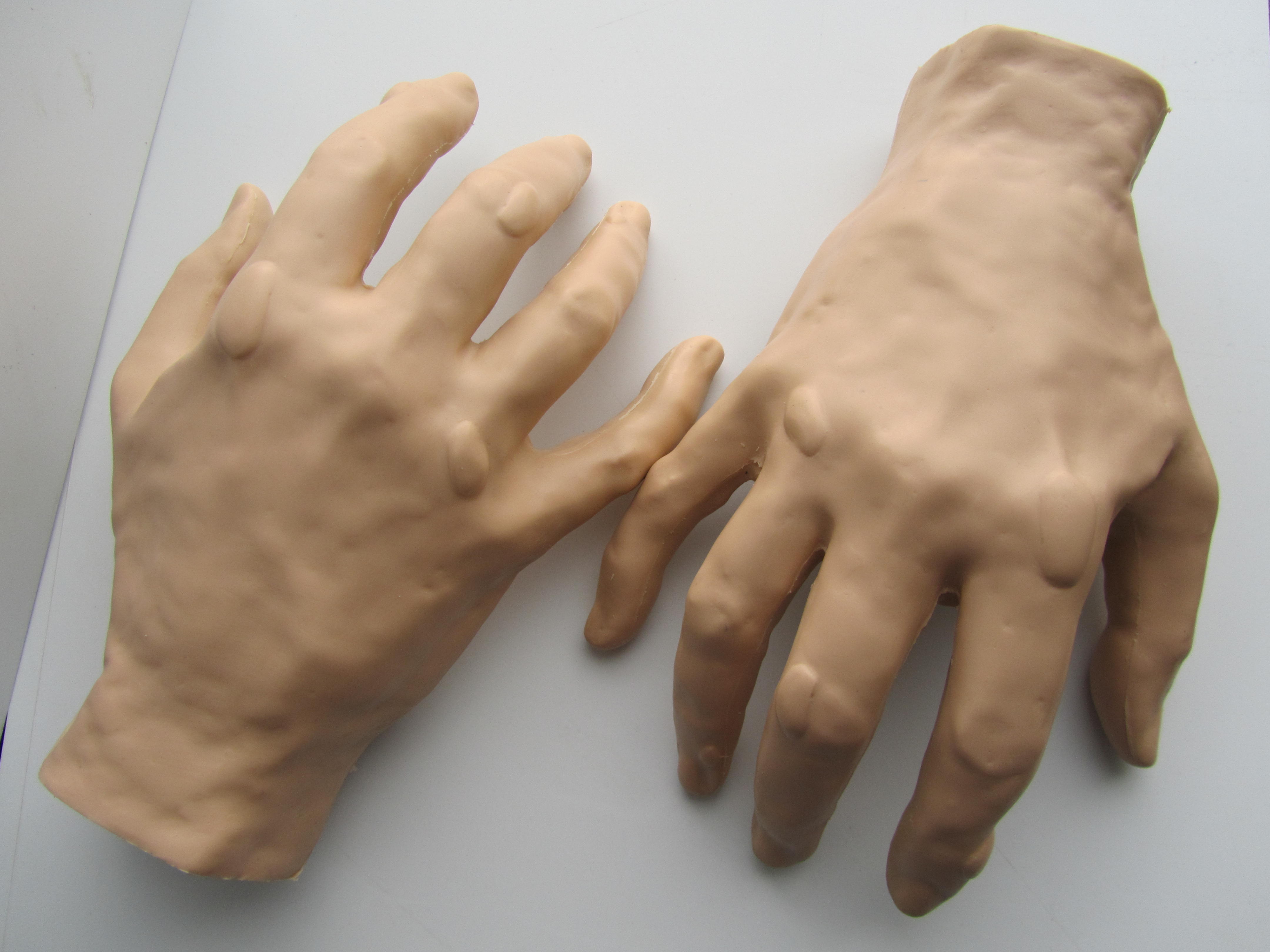
Model Maker’s How-To: Molding and Casting Model Hands

Model Maker Joe recently shared the process by which he created a total of 300 model hands for a client in the medical field:
We had a customer contact us with the need of a class room training aid to use in a practical exercise, measuring gout build-up on a hand. I was initially tasked the job to produce 100 realistic hands with gout build-up at designated locations, using particular dimensions for the bumps.
First we set out choosing a hand model. Then I brushed on a platinum-cure silicone rubber (hardness: 10A, tear strength 102 ply, 1000% elongation at break to guarantee a stretchy, nearly untearable glove) over the model’s hand in thin (this rubber is very thick and traps bubbles) layers.

After achieving a desirable thickness, I shelled the mold with plaster cloth while still on the model’s hand. I made this exo-shell in two halves (palm and back) so that I could pull the mold out.

After the plaster cloth was dry it was time to separate the two halves of the shell and release the model’s hand from the silicone glove.

The next thing for me to do was pour a master by putting the glove original in its shell and banding the two halves together. After putting the unit in a standing base (resting on its finger tips, wrist up), I poured a polyurethane casting plastic (hardness: 70D, tear strength 3000 ply, 7.5% elongation at break) with some black tint and put it under pressure.

When the plastic was cured, I peeled the mold back to reveal the master. It revealed many small nodules around the finger tips and palm (most likely do to sweat) that I cleaned off. After the master was cleaned up a bit, another member of the team built up specific (height, width, length) gout swells out of Bondo, per the customer’s request, at particular locations on the hand.

After the art work was done I repeated the same steps above to make three working molds, but this time the polyurethane plastic was tinted with a flesh color.

We shipped the client an initial quantity of 20, and upon their review, found the hands too hard and life-like for their studies. We needed to re-tool and come up with a new game plan – a softer plastic or a fast curing rubber.

I came up with the idea of a two part silicone mold. A hand cast out of a softer material might not hold up to being pulled out of a glove mold and the cast piece would have to be fully cured (no short cuts).

Meanwhile another team member was preparing a new master cast by brushing some blackened polyurethane plastic over one of the previous working casts, to even out the skin texture. After that cured, he fine-tuned the gout buildup back to customer specifications and tolerances.
When he was done, I built three two-part molds (fingertips down, wrist up) and begin production casting of my next 80 pieces. This time I used a polyurethane casting plastic (hardness: 80A/30D, tear strength 2264 ply, 233% elongation at break) with the same flesh tint.

This plastic had a 90 minute demold time, but with the two-part design I was able to turn the mold (pull the product and pour the next piece) in 60 minutes. These pieces came out of the mold with no flash and very little seam line.

The customer was very impressed and the molded hands did what they needed to do. The client ordered 200 more castings.

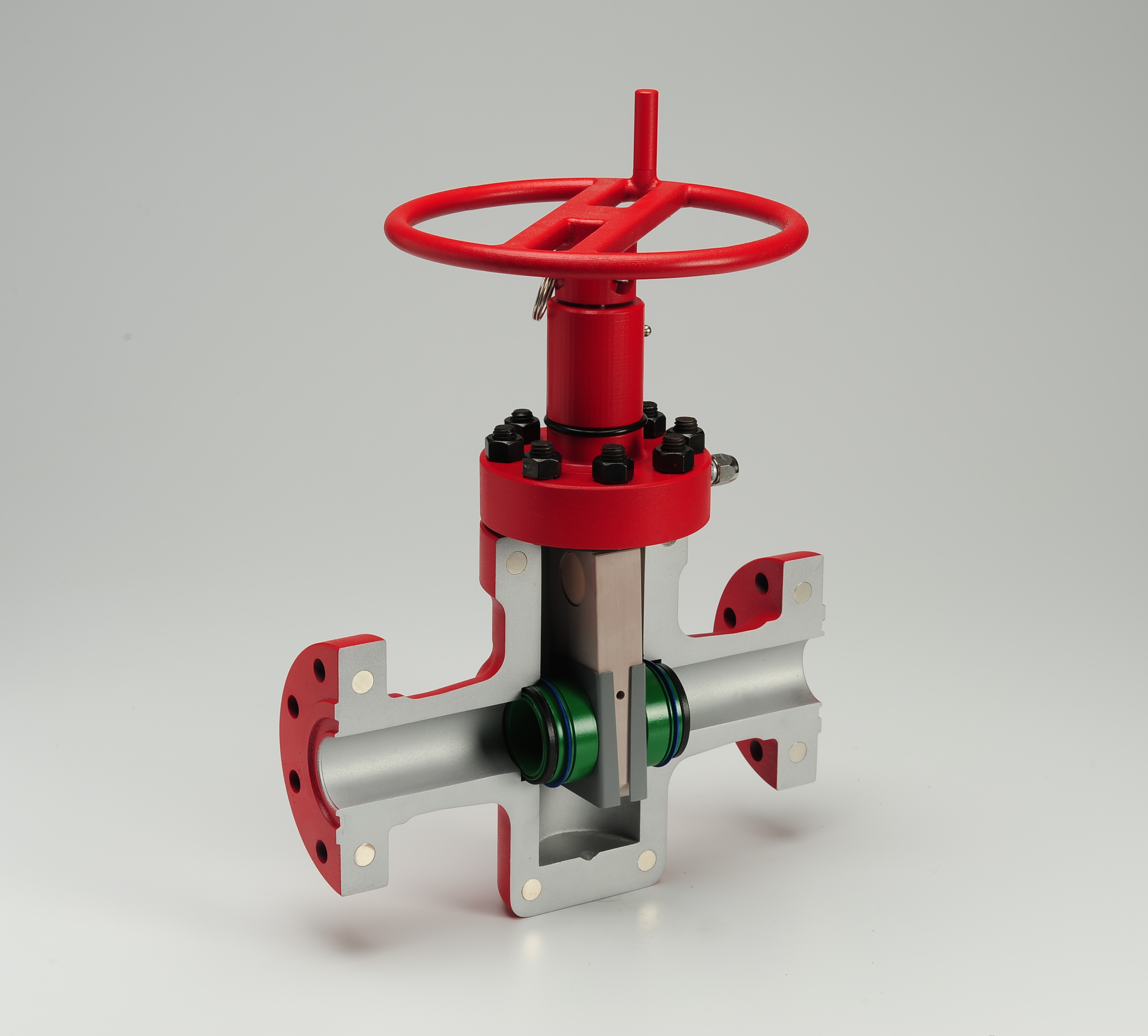
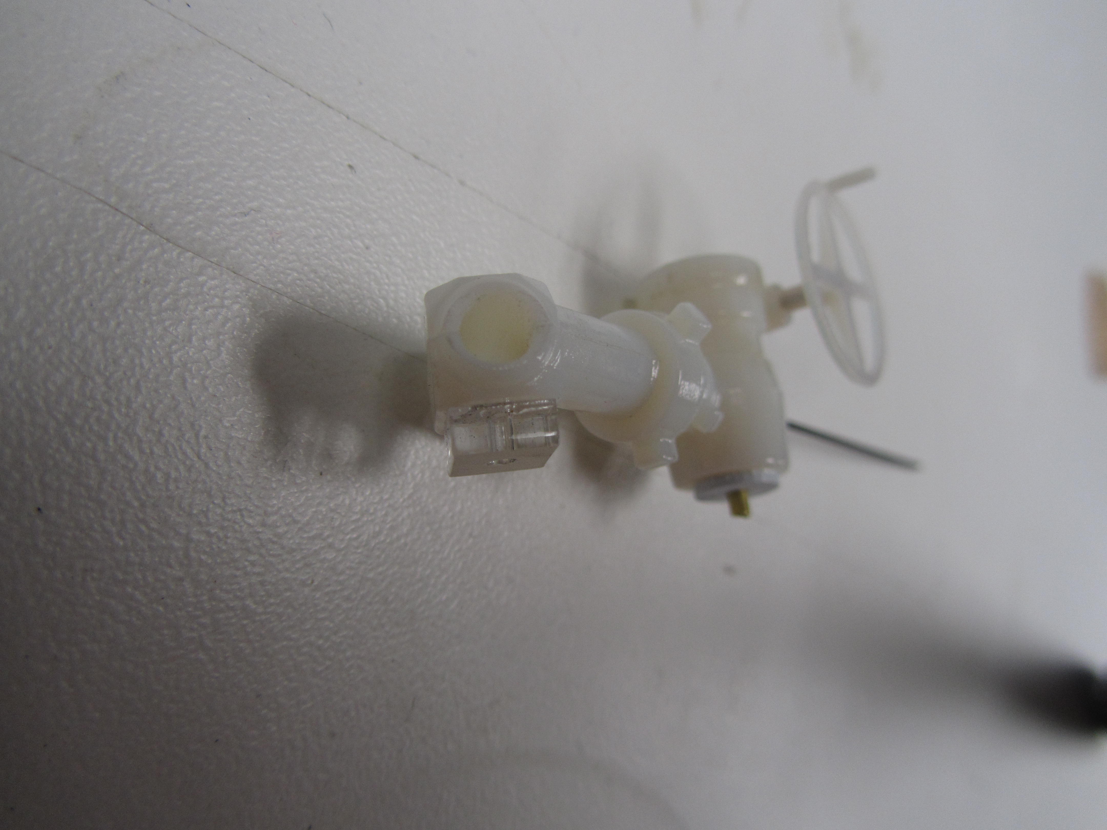
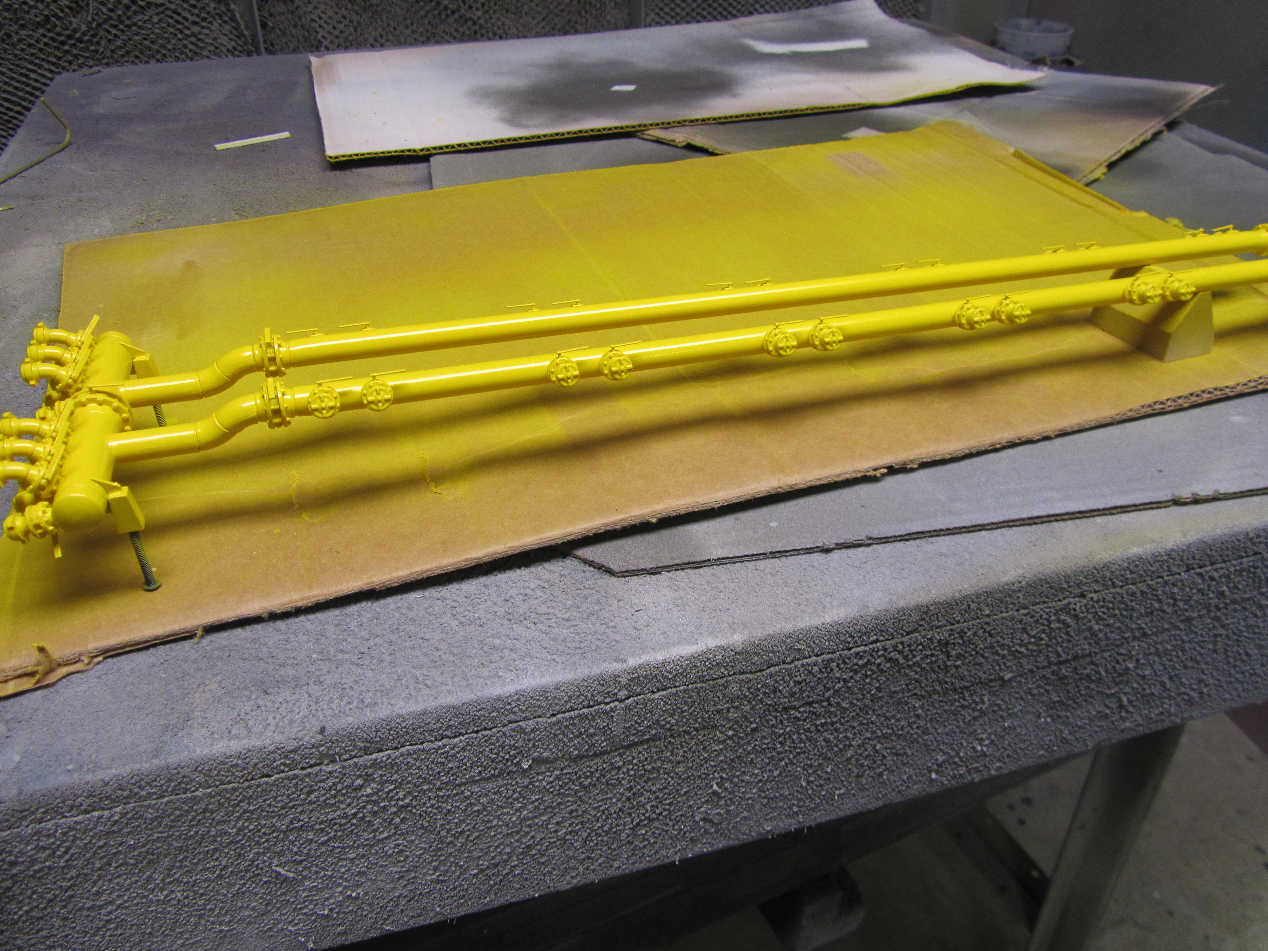
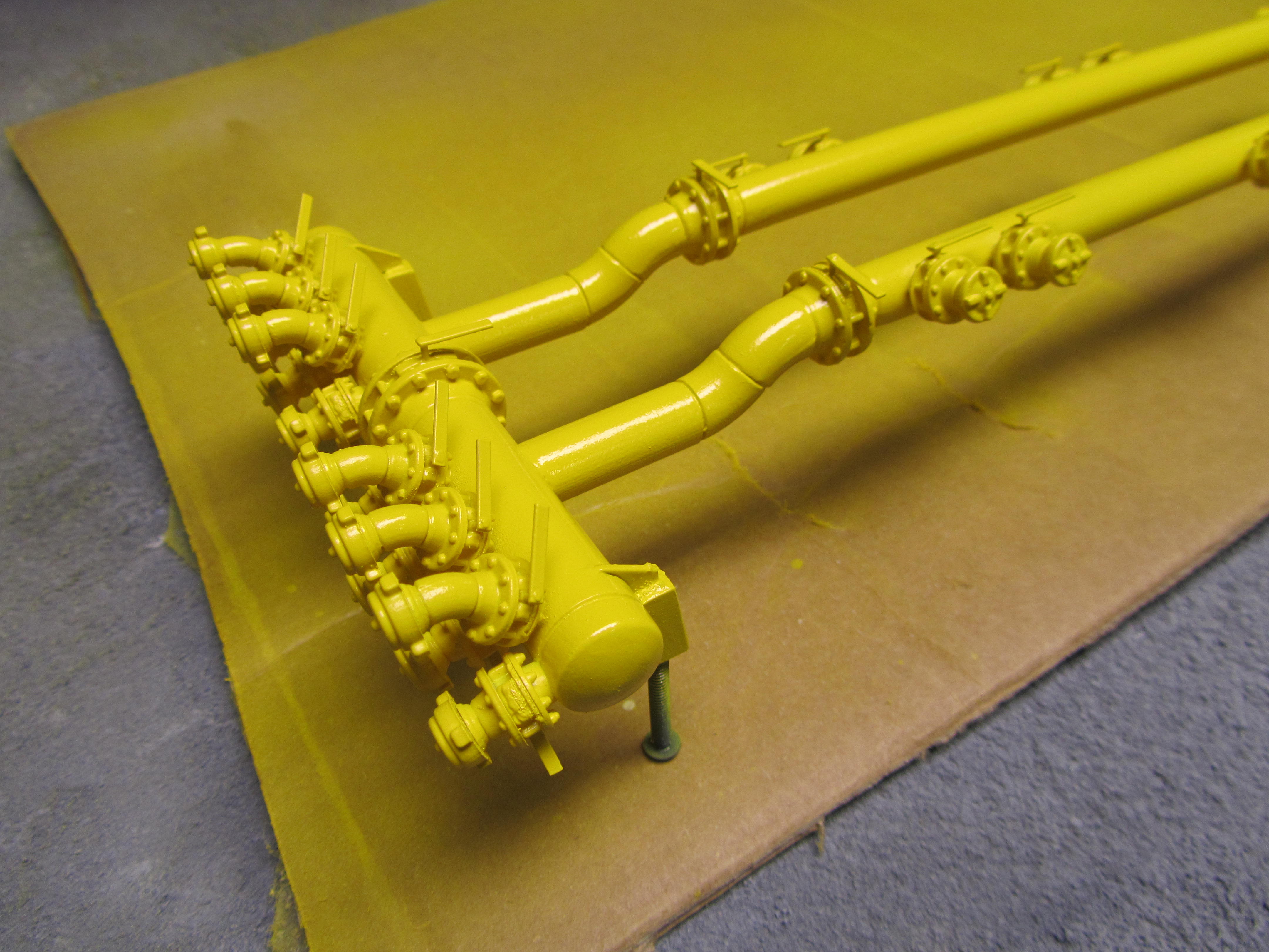
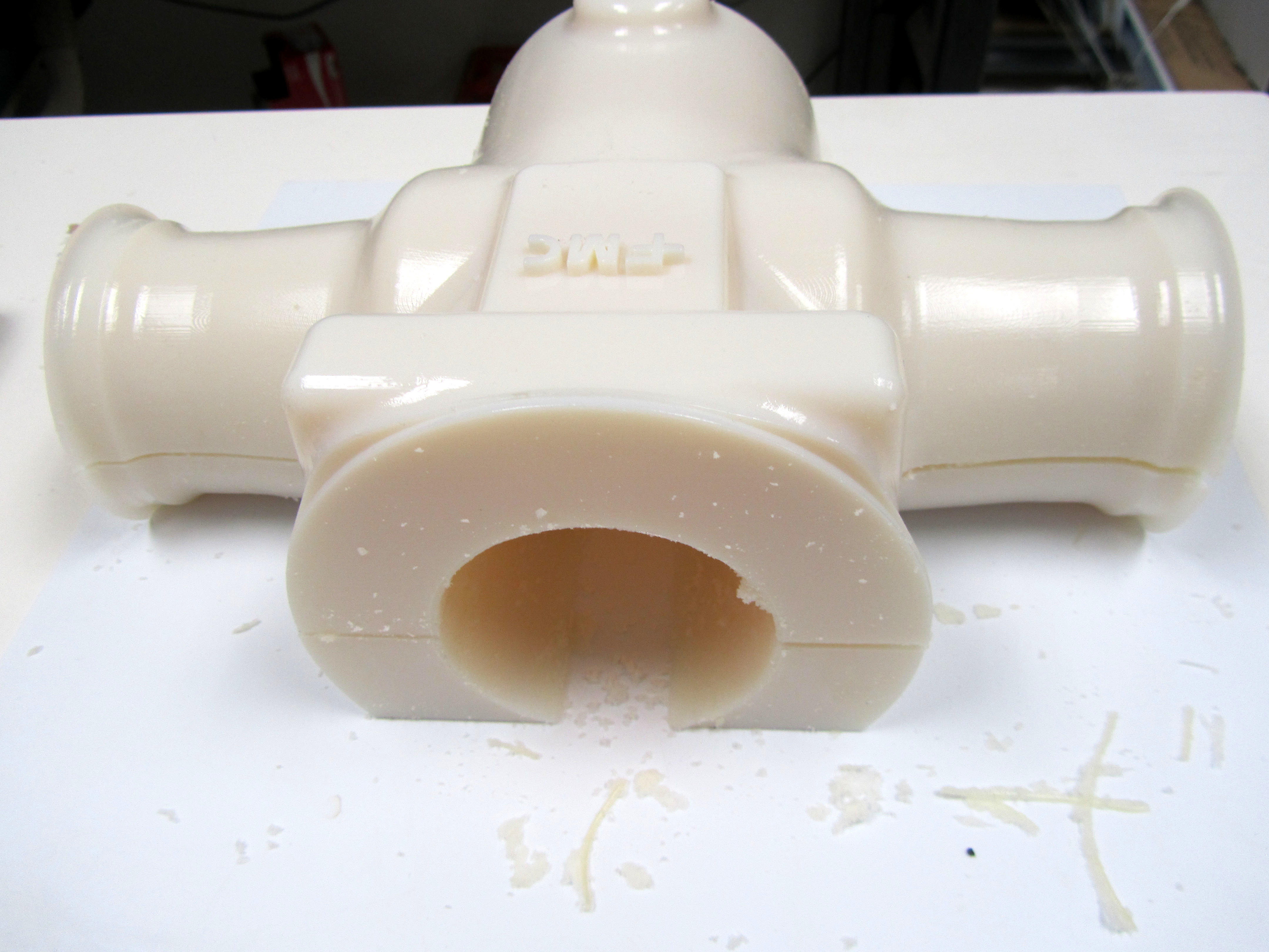
Cutaway Scale Model for Training

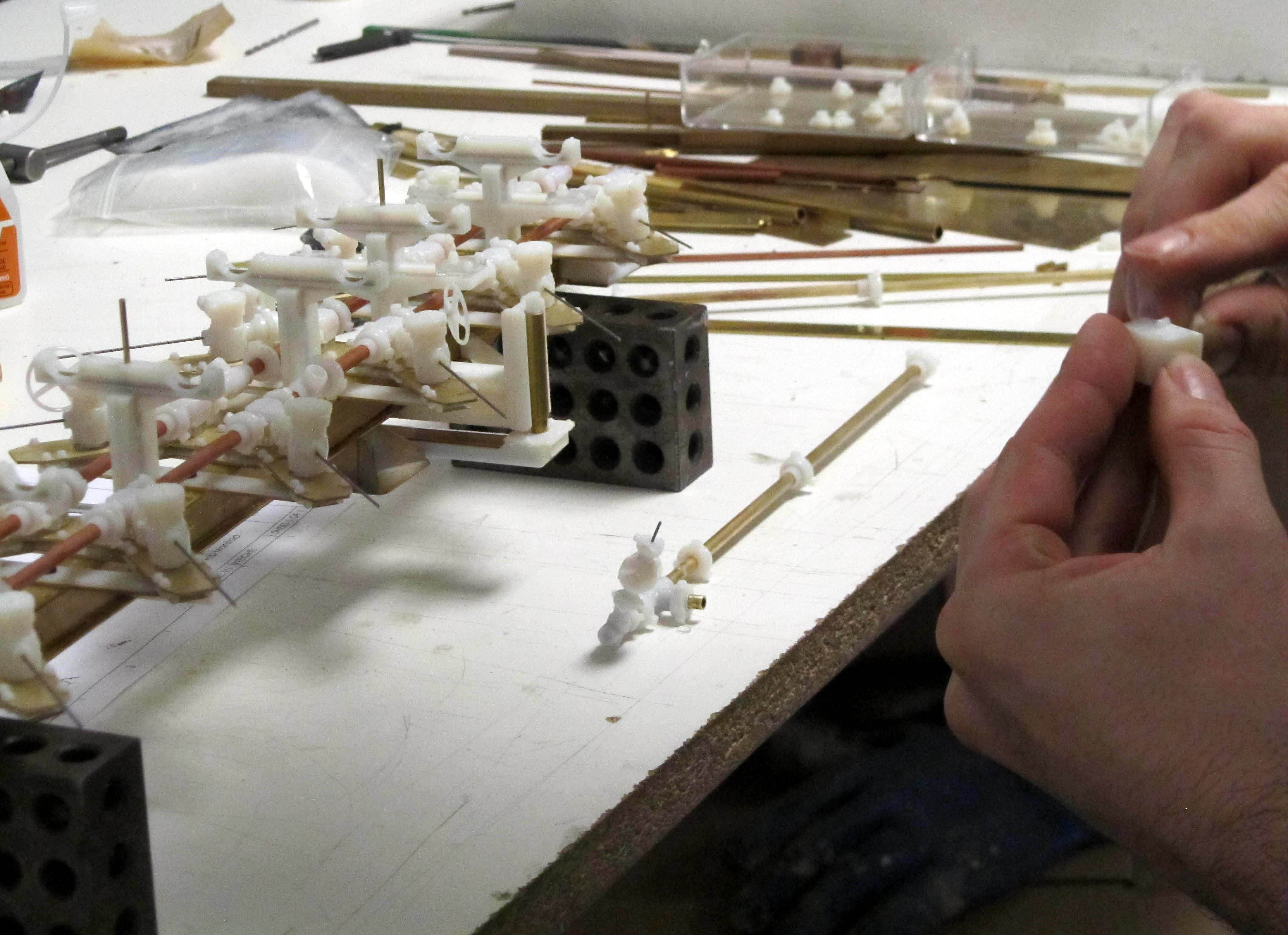
Our client, FMC Technologies, requested a working model of a gate valve that would assist with maintenance training. Talking with model maker, Scott, it was determined that the best way to serve this purpose would be with a 1/2 scale cutaway model that would pull apart and reveal interior components that could be manipulated. Once the general concept was agreed upon, our team discussed the build in general, and the associated costs and time frame, and a detailed quote was written up.

Once the job was awarded, model makers Mike, Dean and Scott came up with a plan of action including a list of materials, fabrication techniques and assemblies, along with a break down of each task and its associated steps. The over all design of the model would include an exterior shell opening and closing with the use of magnets, a working wheel that would move the gate up and down, and numerous interior pieces that could be assembled and reassembled.

FMC provided 3D geometry which was used to create the various parts of the model. Some parts were 3D printed.

Others were formed from machined tooling board. An aluminum rod with threads was created on the CNC lathe. Metal gate sleeves were formed on a press brake, and some off-the-shelf hardware was added as well. As parts were formed, they were attached to each other as required. Magnets were imbedded in the outer shell.


Most of the parts were then primed and painted. Various bright colors were used for the individual parts to enhance the training process.

The whole model was assembled and disassembled multiple times to assure its functionality and durability. The wheel was tested to make sure it moved the gate up and down on the rod correctly. The model was taken for professional photography, then carefully packed and shipped to Canada to our esteemed client.
Click Here for a slideshow of the model build on YouTube.
A Model Maker’s Approach To Mechanization In Models

Recently I took a few minutes to ask one of our model makers about his approach to building scale models. I was particularly interested in models that require mechanics – movement or lighting. Our resident engineer, Dean, seemed like a good candidate for my questions.
Like many of his fellow model makers, Dean starts with an image in his head of the finished model, focusing particularly on placement of seams. He then visually breaks apart the model at these seam lines, and begins concentrating on each individual part that makes up the model. How will he construct each part? What materials will he use to build the part, and with what equipment?
After Dean breaks down the model into parts, he will make a list of materials and fixtures needed for fabrication. He might even draw up a specific part in 3D using Solid Works, and have it printed out full-scale so he can assemble it over top the drawing.
When it comes to models with moving parts, Dean prefers to design the housing that goes around the mechanics first. Creating the structure which frames the mechanical parts helps Dean understand how he will lay out the inner workings.
Motion in a model can take on many forms. Dean determines whether the movement needs to be circular, linear or lever-like, at what speed and whether it needs to be continuous or intermittent. He then chooses the mechanics that will most accurately produce that movement. Will it be pulleys, actuators, motors or gears?
Sometimes the mechanics can closely mimic the original object that is being modelled. This means that the model will be run the same way, albeit in a miniaturized fashion. Most times the motion needs to be represented in a unique way that the model maker must figure out, design and implement.
Off-the-shelf mechanical parts will be ordered in the size and design required for the model project, though usually modifications are necessary. Adaptations need to be fabricated and added on to the stock mechanical parts. Safety is always an issue when working with mechanics, particularly when they are altered in some way. Knowledge of the properties of the mechanical devices and careful placement of the power supply is necessary.
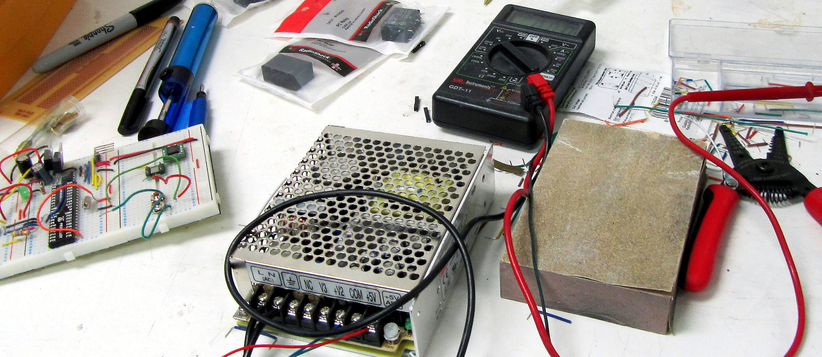
Electrical engineering may come into play with particular special effects in scale models. Lighting or movement can be controlled by switch or circuit board. Dean might be tasked with programming lights or motion to occur at specific times and in a specific order. In these instances he uses a 2D wiring diagram to program the circuit board, which then guides the micro controllers to perform specific actions.
When it comes time to test the motion or lighting of a scale model, Dean is 95% sure it will do what it is supposed to do. Still, there may be some trouble shooting involved at this stage, or minor tweaking. The model’s mechanics will be run for several hours continuously to confirm the integrity of the design. Only then is Dean satisfied that the model is going to perform as expected for his clients.
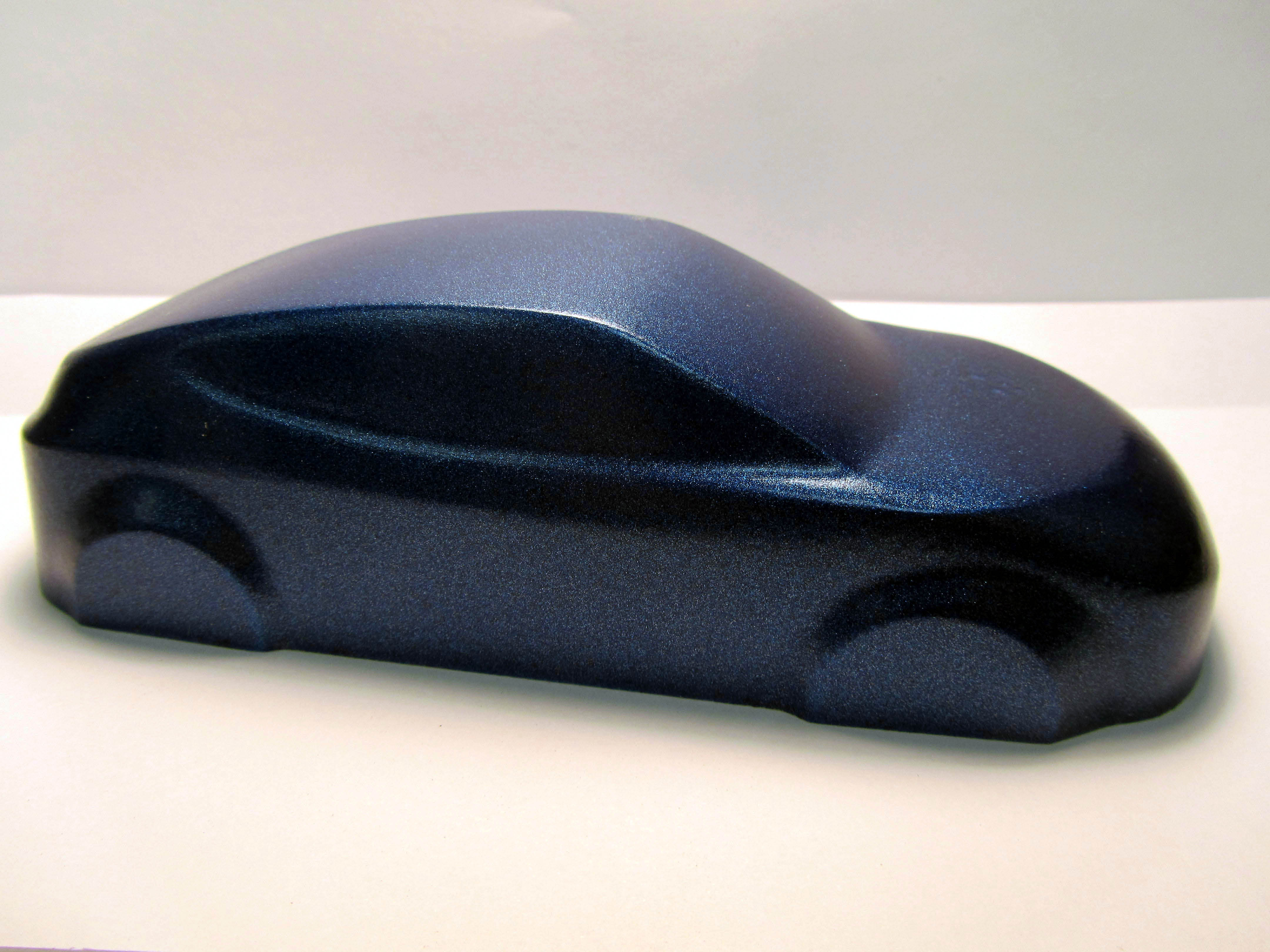
Model Maker’s How-to: Casting Cars
KiwiMill model makers recently designed a car model to be used for a sales display. The models will be used to showcase automotive paints for Hyundai. We chose to cast these from a carved resin master made from our original computer drawings.
A generic car body was created in Rhino 3D by one of our designers.

A CNC milled resin master was created from this drawing.

A negative mold of the core was made from the master.

This core was inserted in the mold to create a hollow space in the cars when cast.

Three molds were made to cast the cars.


The molds were put in a pressure pot for a smooth cast.

130 castings were created.

The bottoms of the casts were sanded smooth.

The resulting cars will be painted various colors by our client, but here is one we painted.

Packing and Shipping Scale Models

Model making companies need to put a good deal of thought into the process of packing and shipping scale models. Custom models come in all shapes and sizes and degrees of inherent durability, based on the materials and methods of construction that are used. No one packing practice will work with all models. Each pack up job becomes a custom design and build in its own right.
Models travel great distances within the USA and internationally, to get to their clients upon completion. Some are shipped through dedicated carriers while others are sent via the major 3 shipping companies. In addition, many models need to be transported to a variety of trade shows throughout their life expectancy. Thus the shipping container must be reusable and extremely durable.

Packing and shipping scale models is a consideration that often comes into play early on in the fabrication stages of a project. A stationary display model may be engineered in a significantly different way than a model that must travel from trade show to trade show, and be packed and unpacked numerous times. Thus the shipping needs of the model sometimes drive the design, rather than the reverse.
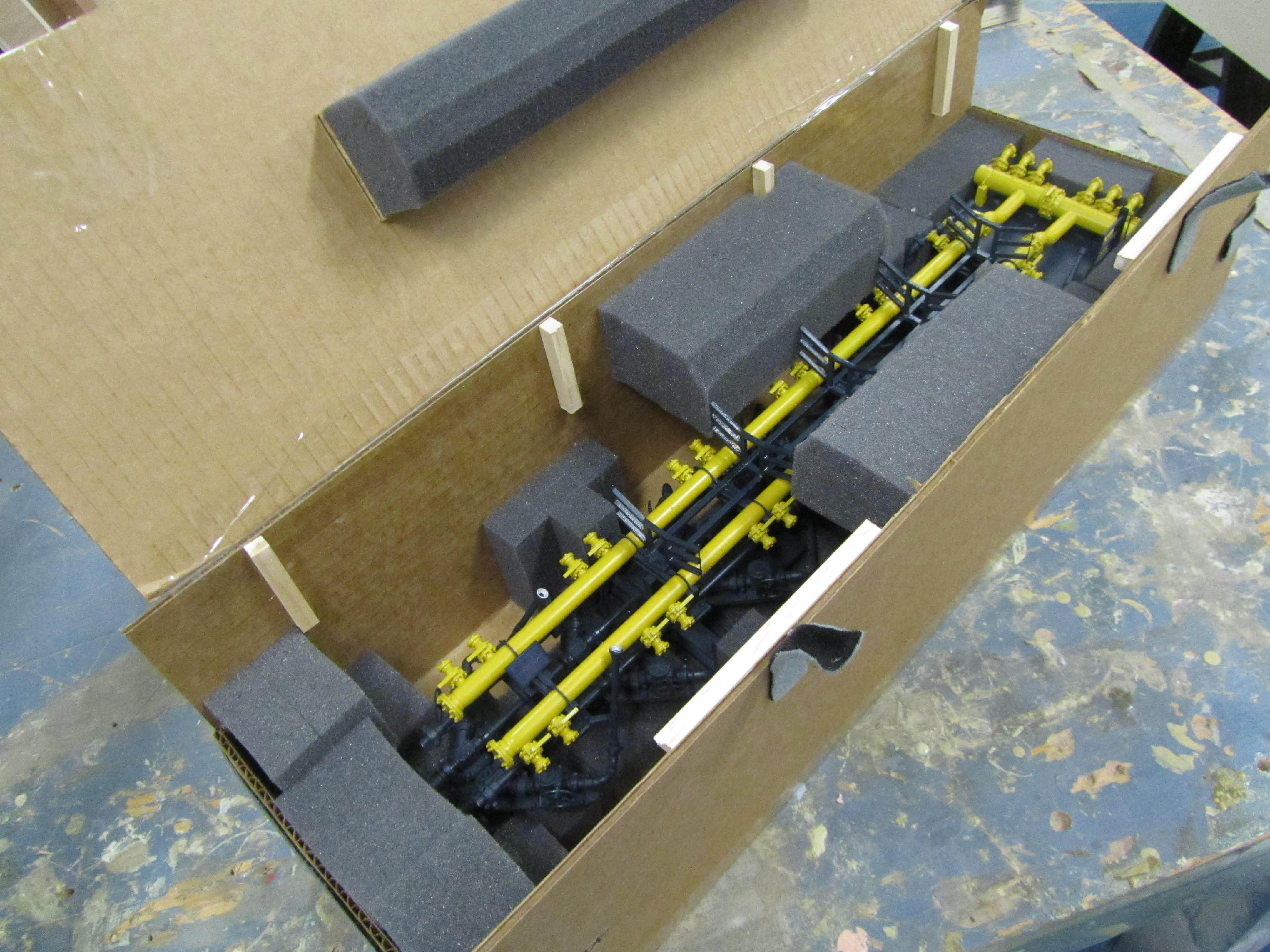
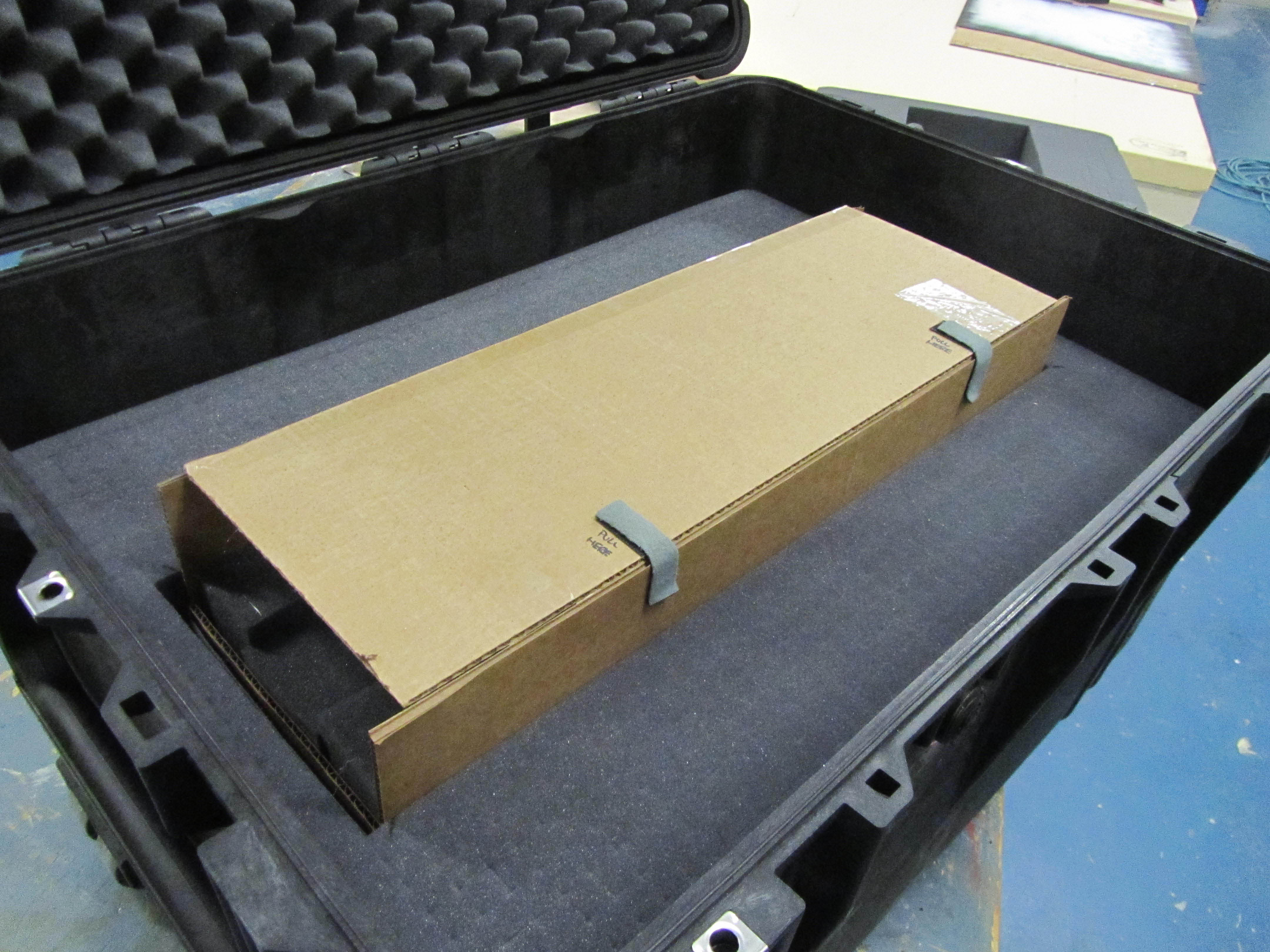
Here at KiwiMill, we utilize a variety of packing cases to ship models. If the model is for trade show use, or needs to travel repeatedly for sales meetings, generally a hard shell container is used. Brands like Pelican, Gator or SKB offer a hard plastic case with handles and hinges, with wheels in some cases, and may even be water proof. They come in a variety of sizes, from brief case size, to one large enough to house a 7′ tall model we recently shipped.
The interiors of the hard shell cases come with foam lining, or will accommodate foam inserts that are purchased separately. In either case, our model makers then custom sculpt the foam “beds” for the model or model parts to rest in.

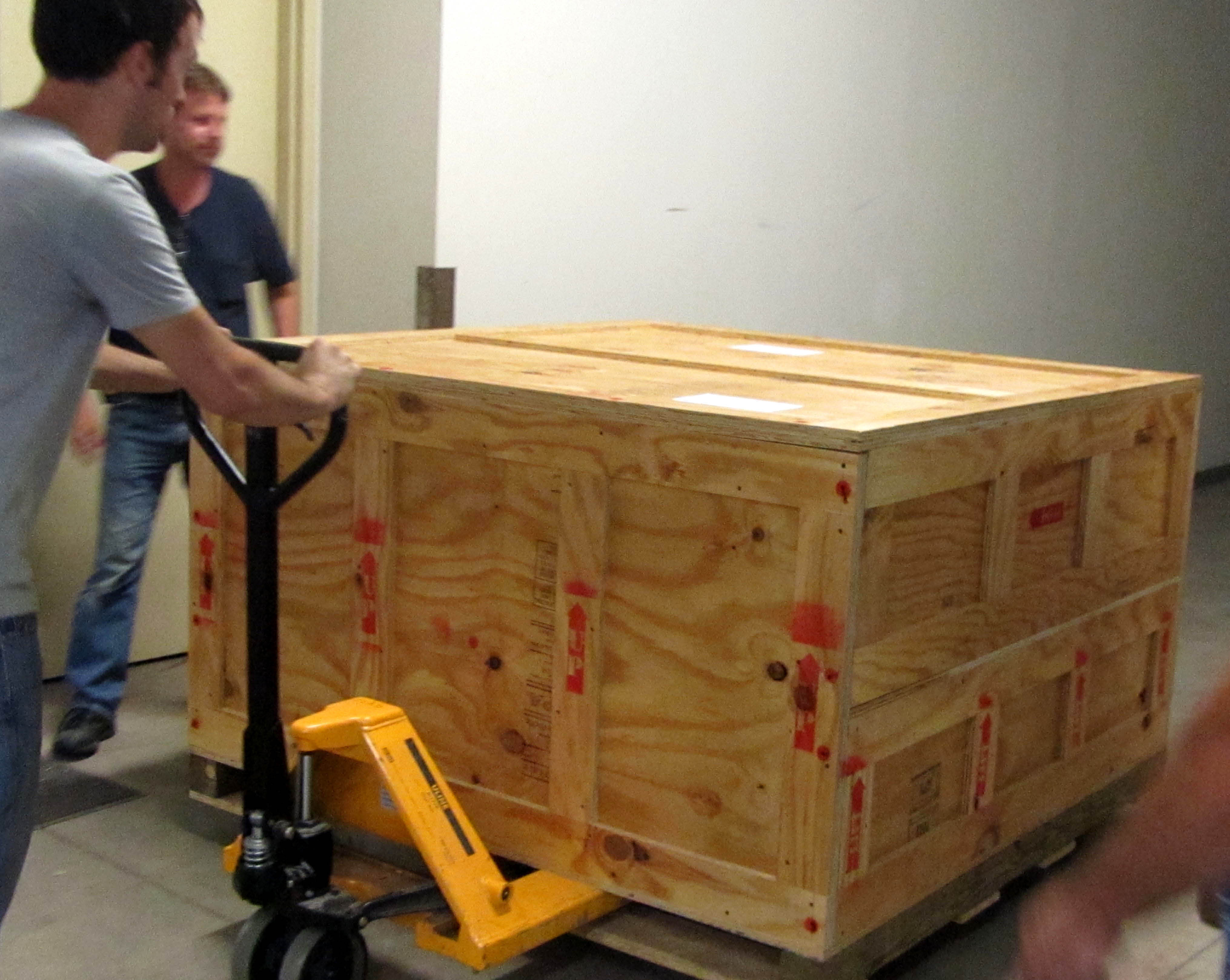
Large, intricate models that do not need a hard shell case, or do not fit in one, require a custom crate build. These wooden crates are built here in the shop and each one is as unique as the custom model going into it. Some crates have shelving to slide a model into. This works well for models with flat bases, such as a traditional site model.

Curvier models, or those with no base, need to be suspended by way of built-in scaffolding in the crate.

All of the crates require custom foam inserts or foam covered blocks to act as buffer points wherever the model comes into contact with a surface, as well as to prevent shifting in transit. Foam is also used for slotting in smaller model parts that need to be assembled upon arrival. Straps may also be required to secure a model in place inside the crate.

Directions are often written into the crate design. Where ever possible, our model makers try to make the packing procedure very clear, indicating what direction to place a model part and in what location. This assures that a variety of handlers can pack and un-pack the model correctly as it travels from venue to venue.

Smaller models that need to make it to a single location may be packed with the use of foam, bubble wrap and double boxing with peanuts. These can be carefully placed in a cardboard box and sent via UPS.

When it comes to choosing a shipping method, some models are given a dedicated driving service. They arrive at our loading dock, are packed by us, and driven to the client with no transfers in between. This method is costly, but offers the security of knowing the model will be handled minimally and arrive at its destination intact. This is an important consideration for some of our clients and may be recommended by our model makers for an extremely delicate and intricate project.

Regardless of which packing and shipping method chosen, it is important that model makers strive to develop the best method for getting each model to the client without damage. Much thought and engineering goes into the design of our shipping containers and the methods used to secure the models inside. There is no point in fabricating high quality products without the packing process to go with it.
Interesting URLS for packing methods used with airplane and ship model builders:
http://www.swannysmodels.com/Packaging.html (packing an airplane model)
http://www.largescaleplanes.com/articles/SparesBox/packing/packing.php (packing a larger plane model)
http://www.modelshipmaster.com/about/shipping.htm (packing a ship model)
http://www.modelusawarships.com/oursppapr.html (packing a ship model)
http://www.dogfighter.com/Custom-Aircraft-Models/shipping.html (illustration of double box packing method)
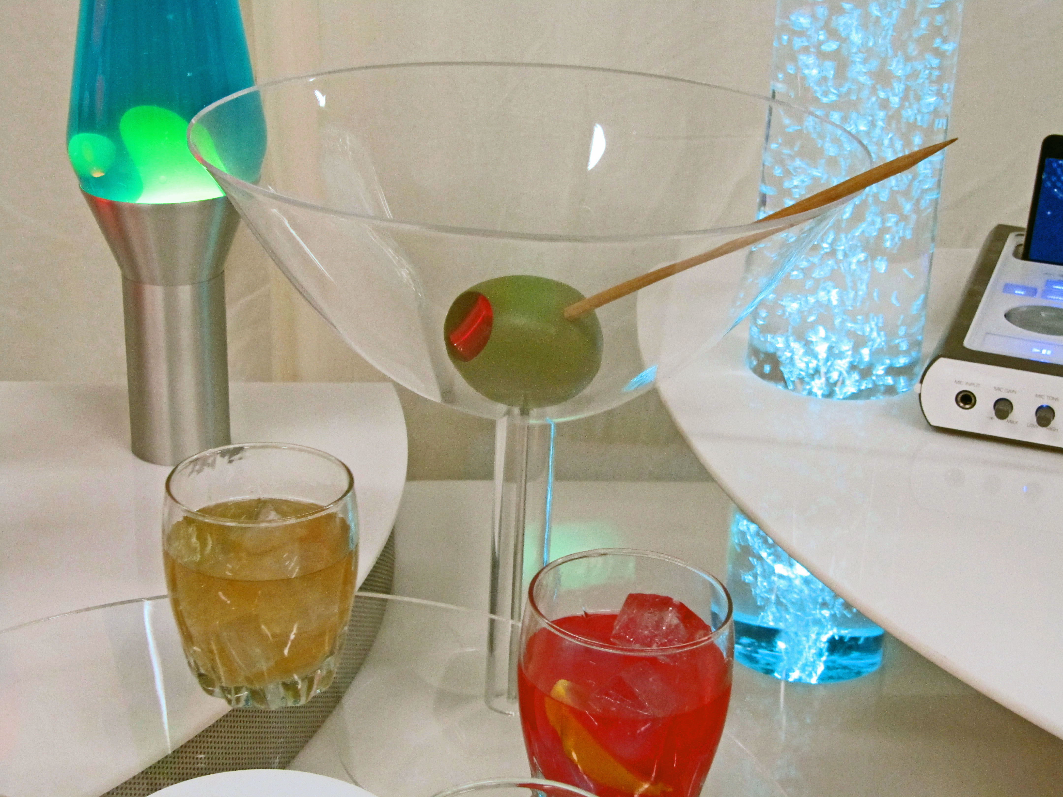
Model Maker How To: Martini Glass Display Model
Making a Martini Glass

Everyone needs to know how to create their own display model of a martini glass, don’t you think?
What you need for this project:
- clear & fluorescent acrylic
- ren board
- plywood & bolts
- wood dowels
- laser cutter
- lathe
- band saw
- disc sander
- drill press
- oven
- paint
- solvent
Model Maker, Scott, started with a piece of plywood, cutting an 8 inch diameter circle in it to form a frame for the lip of the martini glass. He then clamped a piece of clear acrylic into the frame using bolts.
The frame was given legs to lift it off the surface. This gave room for the slumping action to take place underneath. The frame was placed in the oven to be heated.
It came out of the oven with a typical parabola shape to it. Immediately a wooden dowel was pushed down into the center of it while still hot to form the more conical shape of a martini glass. The dowel was held in place until the shape cooled.
While the glass shape was still in its frame it was brought to the laser cutter. The laser was used to cut the martini glass out, following the inside edge of the 8 inch diameter frame.
The base of the martini glass was slumped in a similar manner. Less heat was applied because the slump was much shallower on the base.
Clear acrylic tubing was then put in the lathe and tapered to match the curve of both the top and base of the martini glass. Solvent bonded the three pieces together.
The olive was made from ren board and shaped on the lathe. A hole was drilled through the center of the olive for the “tooth pick” using the drill press.
The pimento was a strip of fluorescent acrylic heated flat in the oven. It was folded over and stuffed into the core of the olive. Then the olive was primed and painted.
Finally, a wooden dowel was tapered with the disc sander and thread through the hole in the olive and placed into the glass.
Voilà!
At this point our model maker went home and fixed himself a real martini.
Click HERE for a picture of the martini glass on display at CES2011, Las Vegas.
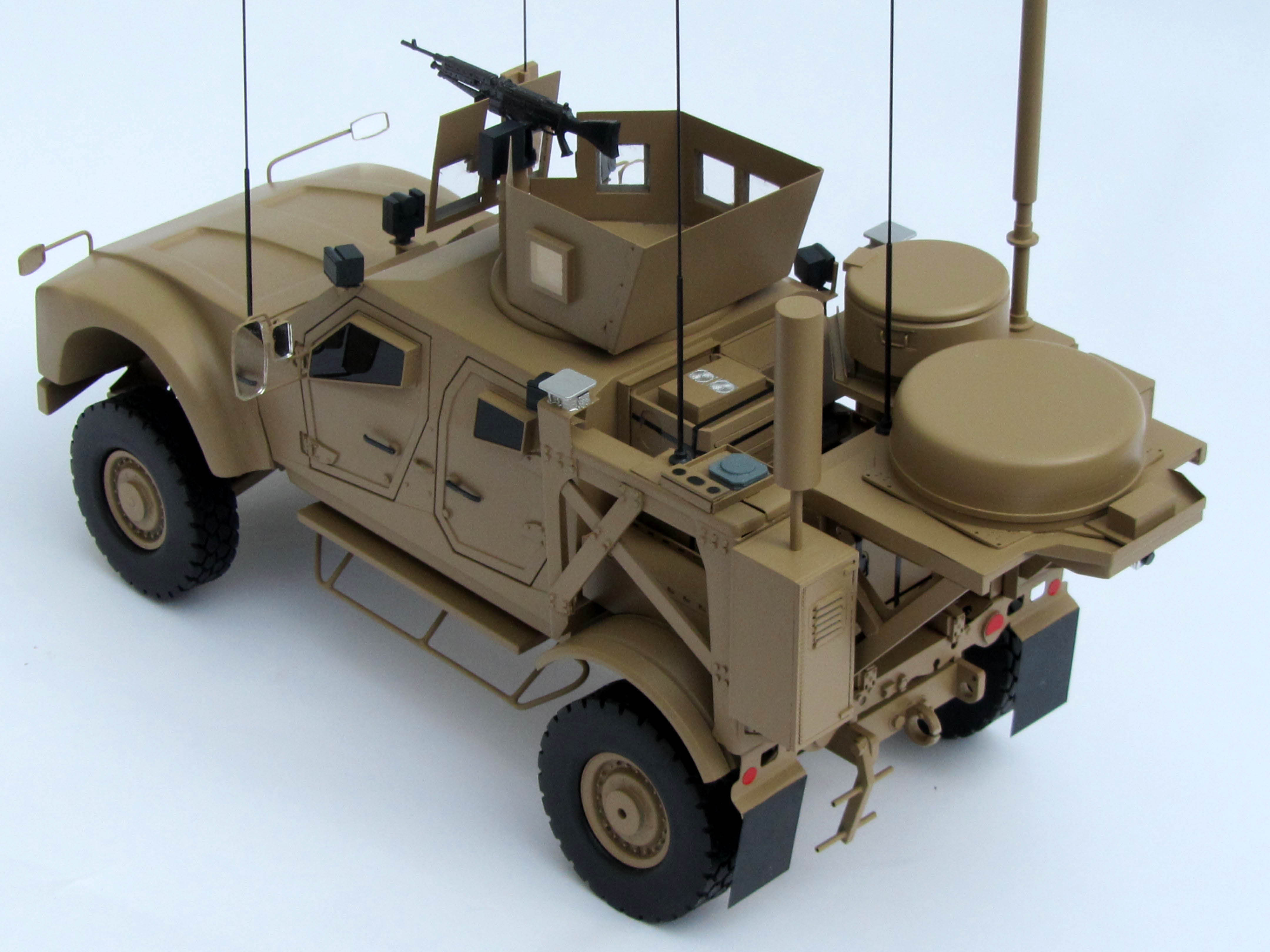
3D Printed Part Transformed
At KiwiMill we use 3D printed parts to make some of our models, depending on the design and purpose of the project.

For a recently made MATV military vehicle, the doors were 3D printed out of plastic with handle, hinge and window details. The part was grown over night in the 3D printer, taken out and cleaned up.

The part was then primed, painted and given additional details.

Here is the door on the completed MATV vehicle. The printed part blends in with all the other materials that were used to complete this model. Our model maker chose soldered and braised brass for most of the model for the strength and endurance necessary in a trade show piece.
New Fabrication Choices for Model Makers

With the addition of 3D printer technology, new in-house model fabrication options are available to model makers. Decisions need to be made about what fabrication method is best for building each model part. What parts should be printed, molded, CNC milled/laser cut, or created by hand? The use of all available technologies in the correct circumstances makes for an efficient, bustling shop, and quality model production. That’s the goal. Not to replace craftsmanship with machines, or to unnecessarily complicate the model building process with flashy new equipment.
Factors that need to be considered when determining fabrication method include; time, cost, accuracy of part, material being used, model type/usage,and the information available on the item being built.
The time constraints of any given project are a major consideration when determining what fabrication method to use to create a model, or its parts. Deadlines are often very tight and sometimes the initial decision to bid on a project will be influenced by how quickly it is needed and whether or not available fabrication methods (and resources) will get the model done on time. An automated machine like a CNC mill or laser may actually take longer to produce a part than hand building, but will use up less human resources in the process. How much available time needs to be balanced with the number of model makers assigned to the project and the length of time each part will take to be made using a particular method of construction.
Costs are often closely tied into time when determining what fabrication methods will be chosen. Time means money, and the amount of labour put into the job is a large part of any model price. Machines can make up for some of the costs in human labour, provided the money is there to buy and run the machine in the first place. Material costs for particular machines, such as the resin needed in a 3D printer, need to be taken into consideration as well.
Model makers need to determine how accurate a part needs to be on the model when deciding fabrication methods. Computer-programmed machining is more consistent and precise than hand building a part. This may or may not be a consideration in a given project. Sometimes a model is an artistic representation of an object, and extreme fidelity to the original design is unnecessary and unwanted.
The kind of material being used in the model will help drive the fabrication method. A 3D printer uses resin. A CNC mill can carve plastic, foam, steel, brass, wood or machinist board. A hand-made part can be rendered out of just about any material available to the model maker. Usually the type of model determines the material being used, and is determined by the model maker, but occasionally the client will have a particular material request as well.
The type of model needed is one of the overriding factors when deciding on fabrication methods. What shape, size and quantity the model will be, as well as its purpose – display, trade show, instruction, sales or prototyping – influence the type of material used to create the model, as well as fabrication choices.
Depending on its shape, a model might be made through a subtractive method of taking away material such as a CNC mill, while other shapes are more suited for an additive method of “growing” a part on a 3D printer. A milled part on the CNC machine needs to be flat on the bottom, no shape can be created underneath the part. This is not a problem with the 3D printer. A completely flat part with an intricate design can be cut on a CNC laser.
The over all scale, or size, of the model may rule out certain fabrication methods. Large parts need to be able to fit on the particular machine being utilized. The quantity of models required influences the construction. Multiple models of the same object can be well suited for mold making. A master model part is made and molded, then multiples are cast from the mold. Automated (CNC) machines in general are helpful for multiples due to their consistency over a hand-built part.
Intended model use will help establish what construction methods are used as well. If a model is going to be moved around frequently, such as trade show use, durability and strength become important factors. This will affect materials used, fabrication, and even assembly methods to ensure a model that will stand up to repeated transport and handling. While a display model permanently housed in a protective glass case can be made of more delicate materials and finer fabrication methods, such as hand-building.
Finally, the information available to build the model will help ascertain the best fabrication method to use. If 3D files are available of the item to be built, that will lend itself better to CNC or 3D printing processes. If the model maker has only a picture or photograph to go by, it will likely be more efficient to build the model by hand, using a well-trained eye, than to try to draw the parts first in a computer program.
A well equipped model shop with a full complement of fabrication methods makes a model maker’s job more effective. Multiple factors are taken into consideration when determining which construction methods to use on any given project. Time constraints, costs, accuracy required, materials used, type of model, and information available about the item to be built all can influence this decision. Many of these factors are intertwined. Ultimately it is a model maker’s job to assess these options early on in the project and plan fabrication methods accordingly.
Mistakes in Model Making
 Model making involves as much pre-planning as possible for each project to avoid mistakes later on. First, by determining exactly what the client’s needs are and determining the model’s over-all purpose. Where will it be used, how often and with what desired impact? Then, by brainstorming ideas for the construction – materials and fabrication methods – model makers determine the best way to go about the actual build. Data about the model is also collected from the client and/or researched, including dimensions, structural details, colors and textures, in order to completely understand what is to be built.
All of this pre-work is designed to minimize problems further along in the model making process. Misinterpreting a client’s expectations can be a disappointing and expensive realization further into the project. Using the wrong materials for a part of the model can threaten its structural integrity. Utilizing a particularly complex fabrication process might cause the project to run over its deadline. Not clarifying conflicting measurements on a drawing might result in a less than accurate replica. Even something as simple as a slightly off paint color can derail a project during the important crunch time before a due date.
No matter how much careful planning takes place up front in a model build, there is always the possibility of mistakes along the way. Model makers don’t necessarily expect them, but they do plan for them and are trained at quickly fixing problems on the fly. Trouble shooting skills are essential in the profession.
Sometimes changes are made by the client during the project. Something on the model needs to be fixed because new information is replacing the original data. This might mean a return to the 3D drawing stage to redesign a part, or simply the integration of a new file sent by the client.
Other times, inconsistencies in materials can make for mistakes in the modeling process. Model makers are prepared for the occasional odd performance of resin, plastic or paint.
More commonly there will be a mistake in fabrication. A model maker spends a good deal of time on the actual build – molding, sawing, drilling, routing, welding, cutting, gluing, painting, sanding or milling. Even the most experienced model maker will occasionally mess up during one of these processes.
Fixing mistakes and making adjustments are part of the model making routine, and generally do not get in the way of a project’s successful completion. Model makers put a lot of effort in the planning stages to avoid costly mistakes later on. However, being gifted with their hands, as well as analytic thinkers, they are well prepared for the challenge of when things do go wrong.